Eng-Tips is the largest engineering community on the Internet

Intelligent Work Forums for Engineering Professionals

  • Congratulations waross on being selected by the Tek-Tips community for having the most helpful posts in the forums last week. Way to Go!

Slots center plane orientation

Status
Not open for further replies.

Diametrix

Aerospace
Jan 31, 2023
50
0
0
US
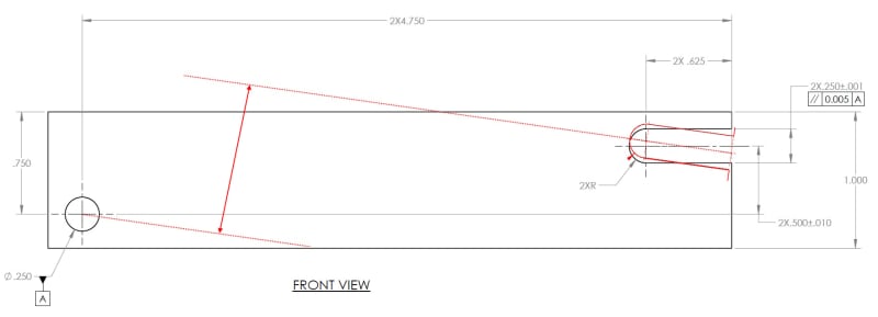
I have two slots and I want to control orientation of their center plane against the axis of the hole in the direction perpendicular to the plane of the front view (picture below)
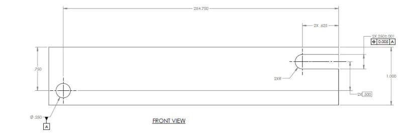
The way I see it, if I use a true position tolerance I will be controlling location of the slot as well. The tolerance zone of the slot will be two planes equally offset from the center plane of both slots by 0.0025". So I will be also controlling the orientation of the slot in the horizontal direction

Slots_Hole_xqxhh1.jpg


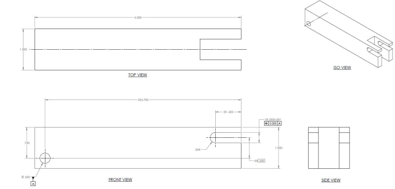
Just the front view for this case

Slot_Hole_1_r2rlde.jpg


Suppose, I don't want to control horizontal orientation of the slots' center plane so tightly and want to control only it's orientation relative to the hole axis. So I do something like that

Slot_Hole_2_trdf6t.jpg


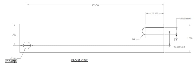
Here I have to switch the datum to the center plane and control the orientation of the axis of the hole. Is that the only way of doing it without introducing additional datums? And additional question, does the dimension 2X .500+/-.010 in the second example control orientation of the slots?
 
Replies continue below

Recommended for you

For the first case what you will not control very well is the location of the slot on the part. This is normally managed by using one of the faces as a clocking reference.
 
Why did you switch them?
Could apply parallelism to the slot relative to the hole if that is your design intent.
You would still need to locate the slot meaningfully. The meaning of the directly toleranced linear dimension between centers is vague. Either position or profile with the necessary basic dimensions would have a standardized interpretation.
 
3DDave said:
For the first case what you will not control very well is the location of the slot on the part
This is a bit of a rabbit trail, but I wonder why? All the points of the center plane of the slot would have to lay between two planes equally spaced 0.005" and basically located from the datum A axis? If I don't care about controlling location to the external sides of the part that should control the location of the slot sides in relation to the hole axis pretty well (assuming I don't care about the radius of the slot). How would you do it alternatively without introducing additional datums?
 
Hi, Diametrix:

Q: "Is that the only way of doing it without introducing additional datums?"
A: No. Of course not. There are a lot of ways to achieve your design intents.

Q: Does the dimension 2X .500+/-.010 in the second example control orientation of the slots?
A: No, it does not as the slot is a datum feature.

If I were you, I would use both slots and end of the part as datum features.

Best regards,

Alex
 
jassco said:
Q: Does the dimension 2X .500+/-.010 in the second example control orientation of the slots?
A: No, it does not as the slot is a datum feature.

It is all relative. Ok, what if I swap the tolerance and the datum like this:

Slot_Hole_3_gzqdmq.jpg


Can the slot tilt like shown in red? Well, no because the dimension between the axis on the hole and the center plane of the slot would change (presumably) beyond the +/-.010 tolerance. So, does it mean that that dimension controls orientation of the slot?
 
Hi, Diametrix:

Yes. It can because the feature (slot) is free to move until you introduce additional datum feature(s). The dimension 2X .500+/-.010 in this case will control parallelism between the slot and the hole.

Best regards,

Alex
 
Alex/jassco,

As the problem is defined, the outer portions are meaningless place holders and have no influence. The OP has answered their own question.
 
3DDave said:
the outer portions are meaningless place holders and have no influence
Correct, with the exception that they locate the axis of the hole. It is intentional. This is just a simplified example. Think of a sheet metal part where you can control the axes of those features but the sides would be highly unreliable.

jassco said:
Yes. It can..
Meaning the dimension shown in red can be more/less than the tolerance specified? Let's say that the dimension shown in red in the last picture is 0.600". Are you trying to say that that part would not fail inspection based on this drawing?

jassco said:
The dimension 2X .500+/-.010 in this case will control parallelism between the slot and the hole.
In a 3D space parallelism between the axis of the hole and the center plane of the slots is controlled by the FCF. The 2X .500+/-.010 is a 2D control. In the plane of the drawing the hole axis is represented by a point and the slots center plane is represented by a line. Now, how can a line be parallel to a point?

I'm trying to understand this type of dimensioning myself. I came to notice that different people tend to imply their own meaning to toleranced linear dimensions that are not placed on a feature of size.
 
Diametrix said:
I came to notice that different people tend to imply their own meaning to toleranced linear dimensions that are not placed on a feature of size.

This exactly is the problem with these kinds of requirements. There is no single correct interpretation. This is why I suggested considering a geometric tolerance instead.

It is also unclear what makes you think a directly toleranced dimension is only a 2D control. It certainly isn't for features of size.
 
Hi, Diametrix:

Q: Let's say that the dimension shown in red in the last picture is 0.600". Are you trying to say that that part would not fail inspection based on this drawing?
A: No. I am not. .600" distance will fail the specs (2X .500+/-.010).

Q: Now, how can a line be parallel to a point?
A: No. The line is not parallel to a point. It is parallel to what is called "Derived Medium Plane" of the slot (.25 a feature of size).

Best regards,

Alex

 
Status
Not open for further replies.
Back
Top