Continue to Site

Eng-Tips is the largest engineering community on the Internet

Intelligent Work Forums for Engineering Professionals

  • Congratulations KootK on being selected by the Eng-Tips community for having the most helpful posts in the forums last week. Way to Go!

Slotted tube Connection_brace

Status
Not open for further replies.

Veer007

Civil/Environmental
Sep 7, 2016
379
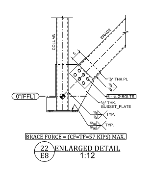
Hey guys, i have a situation where my detailer slotted the tube column at base plate due to its larger brace force, however it seems to be wrong as far as i know, has anyone encounter a same situation?
Capture_hls6bx.png


Thanks in advance!!
 
Replies continue below

Recommended for you

I've seen it, but never don that. I rather think it is a very sound solution than using a large gusset plate. The only thing bothers me is I don't know how to analyze the gusset as shown now.
 
If that diagram is at all to scale I'd still want to check the buckling strength of the eccentric 1/2" plate.

That is a big brace for a 1/2" eccentric plate brace.
 
Just to add to this. Surely it isn't up to the detailer to design critical connections. This one seems to need some pretty close attention and from what I can see the detatiler has done a reasonable job by choosing to slot the column. But there there is plenty going on here so I'd expect that it be fully engineered.
 
As I am aware off, the detailer's office usually have structural engineers (licensed, or by trade) to perform one job only - design the connections.
 
Guys, slotting HSS column at base would not be an issue?

Thanks in advance!!
 
retired13 said:
As I am aware off, the detailer's office usually have structural engineers (licensed, or by trade) to perform one job only - design the connections.
Okay. That makes sense. Different regions, different approaches. Also makes sense that the connection at least seems to have some thought put into it.

I would still look into the eccentric nature of the loading of the 1/2" plate. It is a commonly overlooked item and has resulted in failures. 1/2" seems too small for that brace if the diagram is to scale and if it is a single offset plate (as opposed to a sandwich plate.

Veer007 said:
Guys, slotting HSS column at base would not be an issue?
Why would it be? You are adding more steel.
 
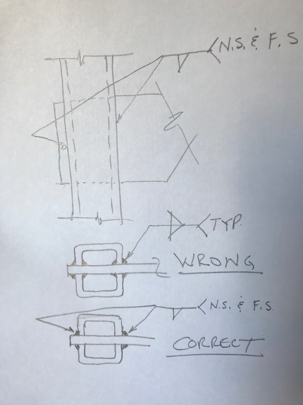
Those 1/4 in weld symbols are wrong. Essentially they are demanding that you weld on the inside of the tube column to the gusset plate. They should rather have only used the fillet symbol on the bottom of the weld line, used two arrows, one pointing to the right side of the column and a separate arrow pointing to the left side column-gusset interface, and then include a comment “Near Side and Far Side.

 
Veer007 said:
Guys, slotting HSS column at base would not be an issue?

What is it that's bothering you about the slotting of the column? Loss of material? Simply the fact that you haven't seen the condition often?

In my opinion, slotted gusset connections are one of the very best versions of these style of connection. It is one of a very small number of connection typologies that will convincingly produce concentric load transfer between the brace force and the column vertical force. Given how narrow your column looks relative to your brace here, that feature may be important to reduce column moments.

The main reason that you don't see slotted gussets more often, in some markets, is simply that they are more expensive to fabricate than other, non-slotted connections.
 
retired13 said:
The only thing bothers me is I don't know how to analyze the gusset as shown now.

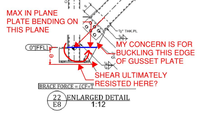
I hear it. Particularly so since, in this case, the gusset probably needs to resist in plane bending as a result of the brace work point coming in above the final point of shear resistance (base plate I assume). Were it spatially tolerable, I might like to see a stiffener on the underside of the gusset just to take compression edge buckling off the table when the brace is in compression.

JAE said:
Essentially they are demanding that you weld on the inside of the tube column to the gusset plate.

That's interesting and something that I've always been confused about. Is the way to interpret near/far: both sides of this solid plate element?

For the sake of argument, imagine that our column here was really a double channel. Would OP's weld symbol be appropriate then?
 
KootK,

Your interpretation of weld symbol is correct. But looks like this guy missed two locations, one on top edge of bracing-gusset connection, another one on the back edge of column-gusset connection. But since all welds on the gusset is the same size and type, the omission shouldn't be a big problem though.

Guessing from the geometry, the 1/2" connecting plate may suffer approximately 15 kai compressive stress. It's ok, or not?
 
KootK, per AWS, a double fillet weld symbol is telling the welder to weld on each side of the steel-to-steel interface, which in this case would be the two sides of ONE tube wall where the gusset cuts through the tube.

This is probably not the intent of the person detailing the weld and is probably not even possible to perform.

I believe the correct weld symbol would be as shown:
Weld_dsyn21.jpg
 
Yes, a little note makes things much more clear. But, unless for very short weld length, the welding of inner tube will not be performed, only the engineer may have to response to a nasty RFC then.
 
Thanks for the info JAE. For curiosities sake, however, I'd still like to know your answer to this:

KootK said:
For the sake of argument, imagine that our column here was really a double channel. Would OP's weld symbol be appropriate then?

 
retired13 said:
Guessing from the geometry, the 1/2" connecting plate may suffer approximately 15 kai compressive stress. It's ok, or not?

I couldn't say as I've made no attempt to evaluate it. However, were I do do that:

1) The compression stress would include the effect of bending, as shown below.

2) My evaluation would include a look at plate buckling rather than raw comparison to Fy.

c01_rtye5v.jpg
 
KootK,

What program you are using for the mark ups? Quite impressive.
 
Double arrows as @JAE are the clearest way to show welds. In my experience, it seems only detailers/connection designers gravitate towards using double arrows to show the correct intent.

 
It's called Bluebeam and I almost consider it to be my most valuable piece of engineering software theses days. Kind of like a combination of AutoCAD and Adobe Acrobat on steroids.

retired13 said:
Quite impressive.

What's really impressive is the speed with which you can do stuff like this in Bluebeam if you're willing to accept some imprecision. I've timed myself and I can usually snag somebody else's sketch, screen in down, mark it up, save the image file, and post it here in under 5 min (depending on complexity). I feel kind of bad about it in some respects as I used to post a lot more hand sketches here that I was proud of. Now I'm a purveyor of sloppy NTS images. This makes me much more efficient though. I figure it's better to post three sloppy sketches a day than one Picasso.
 
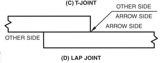
With respect to the weld symbols, I decided to go back to the source (AWS) to review the exact language used as it's been a while. The language I found was "other side of connection" and "other side of part". While I find those to both be a bit ambiguous in this respect, there were also a bunch of sketches and not a one of them suggested anything other than JAE's interpretation. The only one that drifts a little is the sketch shown below which starts to feel a bit like my channel example (why I asked of course).

c01_mrdsqh.jpg

c02_kuzwje.jpg

c03_fhyzqo.jpg
 
Are the sketches purely mouse-work? Or are you using a stylus as well?

Bluebeam is great. The tool palette is super handy.
 
Status
Not open for further replies.

Part and Inventory Search

Sponsor