Continue to Site

Eng-Tips is the largest engineering community on the Internet

Intelligent Work Forums for Engineering Professionals

  • Congratulations KootK on being selected by the Eng-Tips community for having the most helpful posts in the forums last week. Way to Go!

Smallest Radius in Stepped Shaft - Stress Concentration Factor 3

Status
Not open for further replies.

Bewler

Mechanical
May 8, 2019
11
I wanted to know if anyone had a background in tool design. Ignoring the stress concentration factor calculations, what is the smallest manufacturable radius for a stepped shaft(milling bit)? Is it impossible to bring a stepped radius down to less than .001" on a milling tool?
 
Replies continue below

Recommended for you

You want the tool to cut a <.001 radius, or to have a step with an inside radius <.001? The first is do-able, though the tool will wear back pretty rapidly. The 2nd one is trickier, you will go through several grinding stones to get it there (talk to a good tool grinding shop about what is possible).
 
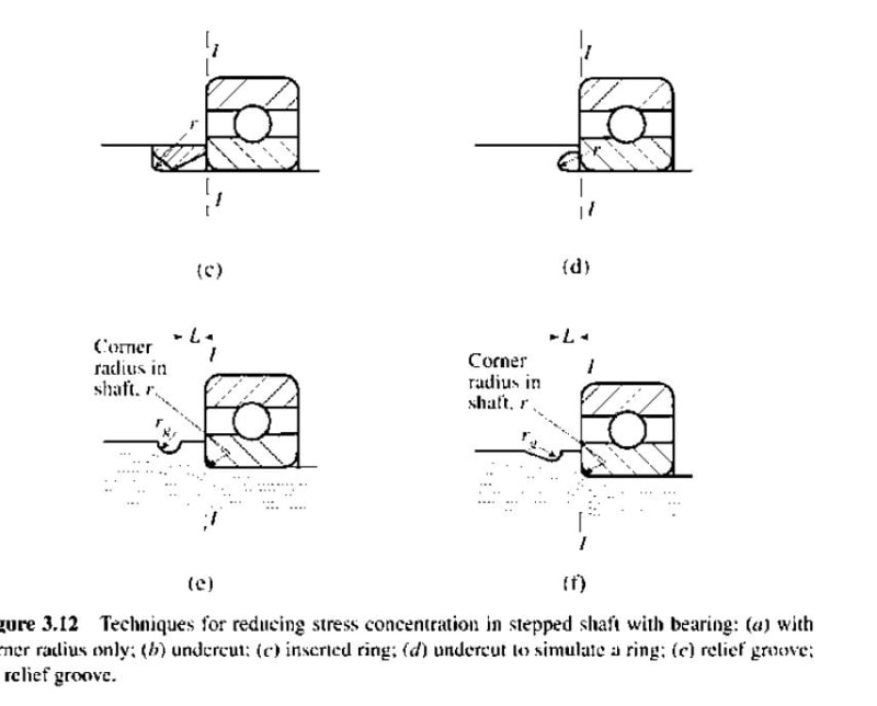
That's what undercuts are for. They provide a "virtual sharp" corner for you. And they prevent serious stress concentrations.
 
yeah, I went there (undercutting) too, but he seems to want a sharp corner ?? not sure why, I mean if he wants to have some "thing" sit on the step, and he's worrying about interference with the radius, then break the sharp corner on the "thing" ...

another day in paradise, or is paradise one day closer ?
 
You say "shaft" and you say "milling tool" - those two don't seem to jive. I'd have more faith that a small radius turning tool and an uninterrupted cut could survive longer than an end mill and its interrupted cut.

It's easy to find "rounded end" mills with radii <.015 so I'd WAG that "sharp" is probably <.005 radius.

End mill manufacturers say "sharp" but they don't seem to publish how sharp. I'd contact one of them and ask them.
 
My experience is that 0.005" is the "sharpest" you are going to get reliably on any mill or lathe tool. Any less than that, listen to Jboggs and rb1957 and use an undercut. What are you trying to accomplish with this tiny radius
 
I would also encourage the undercut. It allows you to control the stress riser corner and use more common tooling. I would call for the undercut to extend into the shoulder rather than into the smaller diameter.

Ted
 
a section thru an undercut …

Screen_Shot_11-12-19_at_03.16_PM_d3qwpn.png
 
Manufacturing always crucify me if I specify an inside corner radius under 0.3 mm as the smallest cutting tool insert tip radius is 0.2 mm (0.008"). Anything smaller than that and you have to have it custom made and it will last a very short time. An undercut is better. You can go in either direction with the undercut.

----------------------------------------

The Help for this program was created in Windows Help format, which depends on a feature that isn't included in this version of Windows.
 
The problem is I want to have a completely flat surface for bonding the surface to another surface. If there's a gap it may cause other problems. Also, thanks for the undercut radius concept. I had no idea people did this on cutting tools to reduce the stress concentration factor and was limited to "positive" radii only as that's all our professors mentioned.
 
"... all our professors mentioned" … harking back to your school days, or is this a school project ?

another day in paradise, or is paradise one day closer ?
 
what if you cut the undercut, to avoid a tool radius, then fill the void with "stuff" ?

what if you fit a collar around the shaft, conforming to the tool radius; sort of like a "radius block" ?

another day in paradise, or is paradise one day closer ?
 
edison123,
"that's all our professors mentioned"
That's probably all they knew. I bet the total time inside a machine shop for all your college professors added together was less than one day. Most of them consider that environment to be "beneath them". It is a sad fact, but true.

That's why my father, who was a mechanical engineer that designed 1000's of machines and had 30 patents, told me after I graduated, "Now that your academics are over, your education can begin." Welcome to the university of life, where you continue to learn but never graduate.

Here's an image that explains undercuts.

Just Google "shaft undercut" and study the images closely.

One of my strongest suggestions to young engineers is to spend time studying the drawings in PAPER catalogs. Over the years you will notice certain features you see over and over again, like undercuts.
 
Bewler,

Maybe your professors didn't mention it, but your textbook probably did.
Capture_xsnqz8.jpg
Capture2_l88izl.jpg


In other news, whenever you have two surfaces come together you are always going to have a "gap", it just matters how large of a gap you are willing to tolerate. Usually you have to fill it with "stuff", like rb1957 said. Maybe it is grease, adhesive, an o-ring, etc. Surely your professors taught you about "surface finish".

But back to your issue, if a theoretically, perfectly, flat surface solves your bonding problem, but a .005" (or .001" as you suggest) groove is too much, there is something else wrong.
 
Status
Not open for further replies.

Part and Inventory Search

Sponsor