Eng-Tips is the largest engineering community on the Internet

Intelligent Work Forums for Engineering Professionals

  • Congratulations waross on being selected by the Tek-Tips community for having the most helpful posts in the forums last week. Way to Go!

Snap Fit/Snap Latch Design - Irregular Geometry

Status
Not open for further replies.

CPosner

Mechanical
Jan 26, 2007
139
0
0
US
I am in the process of designing a snap fit/Cantilever Latch. I have found a massive amount of resources and calculators for such design. But they are not so straight forward in my application, such that my application uses the latch in a radial configuration.

I have been following the design guidelines from this document
Snap Fit PDF

I am using the allowable strain design for a removable latch. Based on the above document, for removable, they state to use 60% of the allowable strain. Anyone have any comments on that. I'm also concerned with an estimation of cycles. I've tried to normalize the radial latch for straight beam calc, but I want more accurate results. That being said, I think I have to do an FEA on the latch. For the FEA, I think my approach would be to impose a deflection on the latch itself and get the strain and reactions.

Is there any other input on designing the snap fits or on the approach I am taking?

Thanks
 
Replies continue below

Recommended for you

Hi CPosner:

The aspect ratio of 1.5 to 1.25 seems to be quite stubby, but if you can still remain within the elastic range when it is fully deflected. It should work.

Concerning the 60% strain: I do not see any problem with the 60% strain. Just make sure you provide a physical stop so that the user cannot violate it.

On FEA: From your descriptions above, I am assuming that the snap fit post is essentially a boss with a circular undercut that is split down the middle. If this is true, your beam cross-section is semi-circular. Much of the stress concentration would be at the centerline of this arc. You will definitely need a transition fillet at the base of your snap fit posts. This brings us to the issue of force required to deflect the snap-fit post. The size of the transition fillet, the area of the cross-section of the post, and of course the resin property will all determine what force is required to deflect the snap-fit posts. Knowing this force is important for two reasons:

1) Since it is removable, you ought to know what force is needed to retract the snaps.

2) You need to make sure the undercuts will not be crushed by this force during engagement or removable process.

Finally, regardless of how well, you engineer this snap, if the molding process is wrong. The snap-fit mechanism will fail prematurely. There are too many factors to mention regarding molding process, but just be aware of this.

**My comments are my opinions, and results are not guaranteed**

Eugene Kim
 
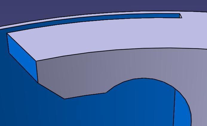
The cross section is still rectangular, but curved on an arc on the "weak axis". The underside of the snap latch, where the locking feature is, is an arc, such that the second part of the assembly has a similar arc to align wit so locking is repeatable and fixed.
 
CPosner:

If possible, can you attach an image of the snap-fit system you are designing? It's hard to picture what you are describing, and a picture is worth a thousand words.


**My comments are my opinions, and results are not guaranteed**
Eugene Kim
 
As per your request, there is the latch.
csnap.jpg
 
From here, it looks awful stubby. I'd expect it to just snap off at the smallest section, since there's no beam to speak of.


Mike Halloran
Pembroke Pines, FL, USA
 
My thoughts also...Stress is too high also. I was hopeful though. I am not ready to trash the design just yet though.

or....I need to reconsider and hopefully I can reconfigure the design to incorporate a snap fit.
 
You can turn it into a curved beam with a nonzero length by relieving the od of the part, just to the right of the cantilever. Sort of a generally semicircular relief, with the left half strictly offset from the hole that forms the beam, so you end up with maybe an eighth of a circle of uniform cross section. That's your beam. You might taper it slightly to get a more uniform stress along the length of the cantilever.

I'd mentally unwrap the problem along a radius halfway through the depth of the thinnest section, model that as a straight prismatical cantilever in Excel, and work from there toward a cantilever tapered in thickness. That should get you close enough.

Yes, you could get a more precise model with FEA, but you can't get material that's consistent enough to take advantage of any precision beyond a reasonable approximation anyway.


Mike Halloran
Pembroke Pines, FL, USA
 
I agree with Mike

Make it a curved beam by removing material from the straight outside edge of the current beam. It could be in the form of a hole in the current beam with the outside edge intact if necessary for other reasons.

Regards

eng-tips, by professional engineers for professional engineers
Please see FAQ731-376 for tips on how to make the best use of Eng-Tips Fora.
 
I'm not so sure I follow..The beam is curved, but I think you're talking about curves through the cross sections. meaning each cross sectional cut would be normal to a curve along it working axis.

That being said, you're both suggesting that the underside of the beam be one constant, larger radius? And I'm not so sure about the relief. A relief in the part shown (i.d. or o.d.) or a relief in the mating part?

I'm a little unclear.
 
I'm talking about a curved top side to the beam, as I presume the mating part controls the rad of the underside.

I do not mean concentric radii as that would give uniform beam section. I think you need a curved but tapered or diminishing section beam so as to distribute the stress evenly along its length as it is deflected to operate.

I am pretty sure that is what Mike also means

Regards

eng-tips, by professional engineers for professional engineers
Please see FAQ731-376 for tips on how to make the best use of Eng-Tips Fora.
 
Status
Not open for further replies.
Back
Top