Continue to Site

Eng-Tips is the largest engineering community on the Internet

Intelligent Work Forums for Engineering Professionals

  • Congratulations cowski on being selected by the Eng-Tips community for having the most helpful posts in the forums last week. Way to Go!

Some confusing questions on splines 2

Status
Not open for further replies.

rollingcloud

Aerospace
Aug 9, 2022
174
I have two spline parts that's used in high load environment. I have MOW & MBW inspection data for both external & internal splines, is there a formula to deduct plating thickness from the MOW & MBW? So I can confirm the class of the spline.

Internal spline Sleeve - Fillet root side fit - ANSI - CLASS 5
number of teeth 27
Face width: 1.4
spline pitch 16/32
pressure angle 30
base diameter 1.461418
Major Diameter(max) 1.816
Form Diameter 1.754
Minor Diameter 1.625
MIN EFF CIR SPACE WIDTH 0.0982
MAX Actual CIR SPACE WIDTH 0.1011
The internal spline was nitrided to ~57 HRC.

EXTERNAL fillet root side fit spline: class 5
Face width 0.25
number of teeth 27
spline pitch 16/32
pressure angle 30
base diameter 1.461418
Major Diameter (max) 1.750
Form Diameter 1.621
Minor Diameter 1.564
MAX EFF CIR Tooth thickness 0.0982
MIN Actual CIR Tooth thickness 0.0953
External spline shows no case hardening evidence and has core hardness of ~44 HRC

Would it better for their hardness to have smaller difference? I wonder why the external spline was not case hardened.

The mating external spline has average lead crowning of 0.0031, lead crowning inspection of the internal spline (see the standard spline data above) shows 0.00005 - 0.00036. Plating thickness: 0.0003~0.0005, can the lead crowning just be the variation of the plating thickness? How do I know if it was an intentional design? From this article, they did a lead crowning of 0.0002 on helical gear.
 
Replies continue below

Recommended for you

Rollingcloud

what type of plate. Silver and copper are plated as break in to prevent fretting during start up.
I said it before but you missed it, example plated threads. the thickness at the pitch diameter is reduced
to allow the addition of plate. it is controlled by pre-plate measurement over three wires then after plate
it is remeasured with three wire by means of a micrometer. it is required to make sure it will assemble.
form , minor diameter and major diameters have to be pinched to allow addition of plate.

normally only external splines are plated. here is an other tip, plate will not plate evenly on concavities.
there for on an external spline there will be more plate on addendum surfaces, than the dedendum surface.
it is the nature of splines. what I do is at minimum actual and maximum actual tooth thickness I subtract the
plate total from the circular tooth thickness of the external spline . then calculate the 2 wire measurement.
but it works better if you have to sets of gauges. pre-plate and post plate. no changes to inspection criteria, just dimensional.
other wise it will be to difficult to manufacture and to many good parts will be rejected.

crowning is based on mis-alignment and there are formulas to calculate the required crowning.
 
an other tip per the specification max effective and min effective tooth space and tooth thickness can only be inspected with gauges, not measurement with wires.
and in essence gives more tolerance to manufacturing , which is a good.
 
mfgenggear

Thank you again for helping out.
It's cadmium plate. I saw one of spline data term called "Plating allowance", now it makes sense, basically the teeth have to be slightly smaller to allow for the plating to ensure fit, for example, min actual TT - 2*plating thickness = pre-plate min. actual TT.
So if given measurement over wire inspection data, I first calculate the actual tooth thickness and then subtract 2*plating thickness to get the pre-plate actual thickness and then compare it to the table in ANSI B92.1 to determine the class?

So plating thickness variation tend to affect profile variation more than lead & index variations.

Is it common to see a lead crowning on internal splines?
I am also planning to get a few Go & Nogo gauges for spline inspection when the production drawing is approved

 
Rolling cloud

yes cadmium is for corrosion protection, and for break in, , tooth thickness your on track now.
no it is not normally on internal splines, but it can be done , it can be shaped or spline ground but not broached.
if inspection criteria are on the blue print it will over ride the specification, if specification and class is given that is the criteria.
 
mfgenggear

Sorry but what's break in? I googled and looks like something to do with warming up new ring & pinion gears.
I guess it's ok for inspection criteria to override the spline spec if the manufactured spline pass Spline Ring and Plug gages and the quality of the spline gauges is good, but how do I know if the spline gauges are good?
It's kind funny that it takes another set of spline to check the splines on the drawing...feel like chicken & egg problem
Have a wonderful weekend!
 
Rolling cloud
Lol ya that's true. A master gauge has a very tight master gauge tolerance per the specification for gauges. It is certified.
To the bureau of national standards.
The max effective on an external can only be inspected with a gauge. The internal spline min. Effective can only be inspected by a gauge. Have a good weekend as well
 
rollingcloud said:
So if given measurement over wire inspection data, I first calculate the actual tooth thickness and then subtract 2*plating thickness to get the pre-plate actual thickness and then compare it to the table in ANSI B92.1 to determine the class?

The actual tooth thickness is arc's length, measured on the pitch circle, while the plating thickness is measured in direction normal to the flank. The most important difference would be that the arc is longer than the normal by 1/cos(α), so in this case 1/cos(30°)=1.155.
 
mfgenggear

The certificates must be very hard to obtain? I was surprised that I was not able to find any standard off-shelf spline gauges online.
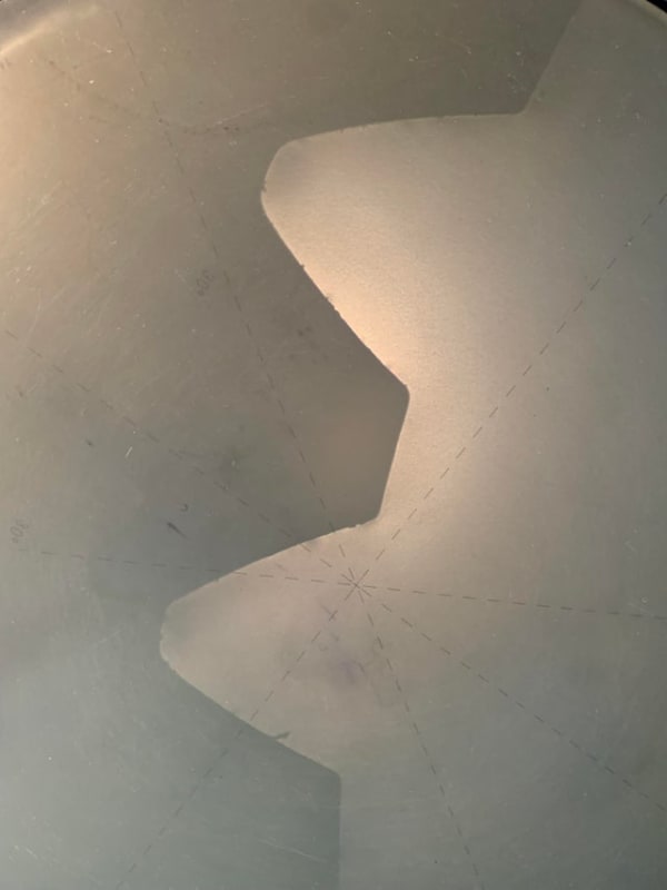
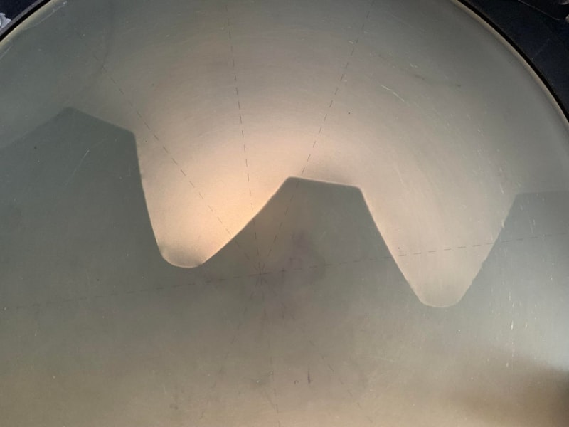
For sanity check, this 32/64 internal spline has fillet root right? It looks like it can be either flat or fillet to me...
xoti31fed7y91_yqygs4.jpg
o9ntz0fed7y91_bu86sl.jpg
 
Rolling Cloud
Contact Ash Gear in Michigan , and broach masters in California. Ash may have in stock. If not it will take an expedite charge to get it in 6-7 weeks, normal delivery can vary from 9-12 weeks. Design and build.
 
Rolling Cloud
Far as measurements go, stick with measurement between pins for internals and measurement over pins for externals until gauges can be obtained. There is dozens of gear programs out there that are cheap
Your inspection and mfg team will appreciate it.
 
Spigor

Thank you for the pointing it out, you mean (for 30 PA) the arc length is 1.155*normal_length? Or you mean the arc length is 0.0001155 longer than the normal?
 
mfgenggear

Thanks, I will save the vendors to the list.
You mean using CMMM gear programs for inspection after the parts are manufactured?
 
I have deducted years ago the plating in tenths in the from circular to perpendicular made no difference, the error was negligible attached is a drawing of the actual spline with minor tip and minor dia, errors.
but the involute is correct. one can now easily graphicly depict the geometry in cad. it is much easier to under stand that way. I never had an inspection issue. just remember the plate at the addendum will be much thicker than at the dedendum. it's not exact science. because of the plating dynamics.
 
 https://files.engineering.com/getfile.aspx?folder=8680e05e-7412-43ee-97c2-65f6cc3da530&file=27t.jpg
rolling cloud

CMM technology is getting very sophisticated. and no doubt it is the way of the future, but I am old school and like an old school verifying between and over measurement over wires.
one use gear wires over the tooth space flanks with micrometers or precision pins between three or two gear wires., I suggest you go online and obtain Dudley's gear book and other and read as much as possible
do under stand all gauge and gear wires have to be calibrated to the bureau of standards. and all must be calibrated
 
Rollingcloud,
I mean that the arc length is approx. 1.155*normal_length. Since your MIN EFF CIR SPACE WIDTH is equal to the MAX EFF CIR Tooth thickness, there seems to be no room for the plating. I'm not sure what the goal is. I would choose the fit, modify the space width and the tooth thickness to allow for the plating and calculate the MOW and MBW to be specified on the part drawings.
What do you want to do?
 
No I said subtract the plating thickness from the blue print actual tooth thickness.
Then calculate the measurement over wires from the modified tooth thickness. That's how it's done.
 
mfgenggear & spigor

Thank you again for the help, the min cir space width and max eff cir tooth thickness came from ANSI B92.1 30 PA 16/32 pitch table. In the beginning I thought I could just use the standard spline, I am surprised that the standard spline does not have plating allowance, afterall, plating is so common.
The inspection vendor told me today that due to the enormous lead modification on the external spine, ANSI B92.1 tolerances is not applicable, and the spline would be unmeasurable per ANSI b92.1. I am a little confused. Maybe because it's impossible to account for the reduced size due to crowning when inspecting min. act TT & max eff TT? that's why i would not be able to determine the class per ANSI. I would imagine I can only use Go & NOGO gauges to inspect the modified spline. But I guess I can still apply the profile & lead tolerances on the modified spline as normal, it just cannot be a specific ANSI Class anymore?
 
rolling cloud tell the vendor to make the gages to the final blue print tolerances. if they refuse find an other vendor till they do.
what ever class the final blue print tolerances and class is that is what it should be made to.
 
Even with lead crowning applied, there still is a spot, usually in the center of the spline's length, with no lead modification. The MOW is defined in this thickest spot. So, you still can use the MOW and/or gauges to inspect a spline with lead crowning. If the B92.1 tolerances are not applicable, obviously no standard gauge can be used to check it.
 
Status
Not open for further replies.

Part and Inventory Search

Sponsor