Eng-Tips is the largest engineering community on the Internet

Intelligent Work Forums for Engineering Professionals

Specifying the orientation of a dimension 1

Status
Not open for further replies.

MattEdwards

Mechanical
Mar 19, 2024
12
0
0
GB
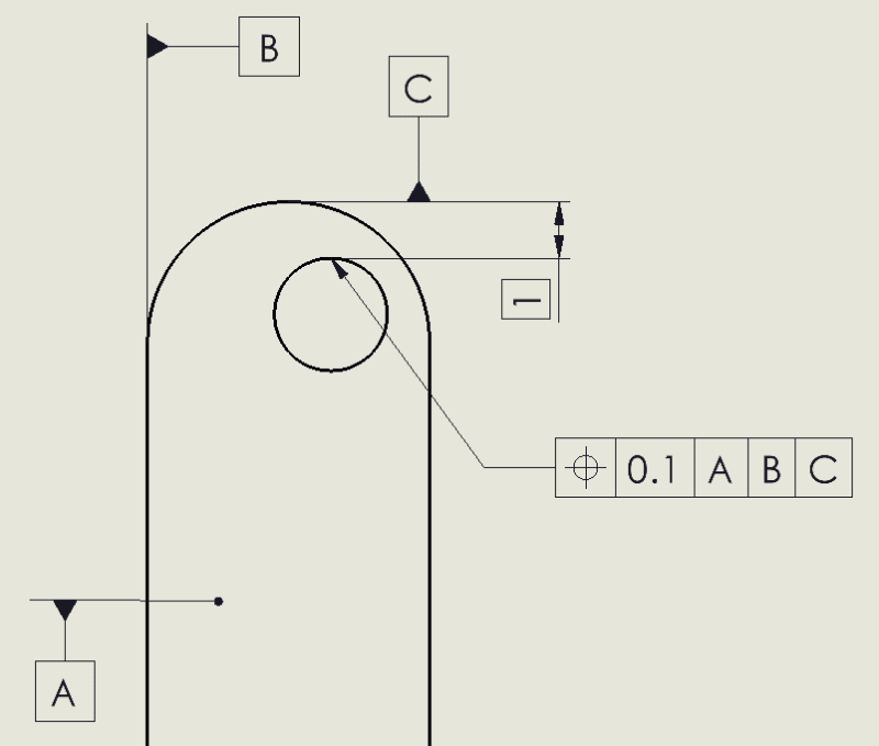
I have a 2D (die cut) part, where I'd like to dimension the distance between a hole and a curved edge. The measurement needs to be taken parallel to the long straight edges of the part; if it's measured at an angle the nominal would change. Is the measurement orientation implied already? How do I explicitly specify the orientation of the measurement?

2024-07-30_09h53_56_ecatrn.png
 
Replies continue below

Recommended for you

Hi MattEdwards,

The way the dimension is shown in your picture means that the measurement would be taken from the tip of the radiused portion to the topmost tip of the hole, with the measurement axis being parallel to the dimension line. Therefore, I believe you dimension matches the goal you mentioned in your post.
 
You need to either supplement with a written note explaining everything, or use a GD&T method (a basic dim, then a position symbol with three datums referenced).
 
Garland23 said:
use a GD&T method (a basic dim, then a position symbol with three datums referenced)

Where should the position callout go? Do I need to state that datum C is perpendicular to datum B? And if I reference datum B in the FCF, does the position tolerance then control the distance from datum B (which I don't want to do)?

2024-07-30_14h11_40_wtjb07.png
 
Garland23, it seems that the OP just wants to make sure that the measurement is taken parallel to the long sides. Isn't the original drawing sufficient to express that? GD&T could help, but I'm not sure it's absolutely necessary.
 
MattEdwards and donatim24, I guess the use of a position symbol isn't required, but ASME Y14.5 (the standard for dimensioning and tolerancing here in the US) says that if traditional coordinate dimensioning is used to locate features, then it has to be done "from two or three mutually perpendicular planes" (paragraph 4.6.1). That sure sounds like datums need to be invoked, and I'd say that their order of precedence needs to be indicated.

That same standard also discusses this problem of ambiguous direction/orientation in its Appendix I, on pages 306-307.

Therefore, some sort of GD&T-style datums should be labeled to clarify that the distance is to be taken in a direction parallel to one of the long edges. Matt, your situation poses a curveball because you want to control the edge of the hole, not the axis (which is typically how the position symbol works). Some folks might suggest a profile tolerance, but I think a good option might be to keep the A, B, C datums as you've already labeled them, but keep your original number of 1.0 (without a box around it). Then add a note -- either a blanket note for the drawing or one specific to that dimension -- saying "dimension(s) to be measured from datums A, B, and C in that order of precedence." The result is a hybrid of traditional and GD&T styles, but it would remove any ambiguity.
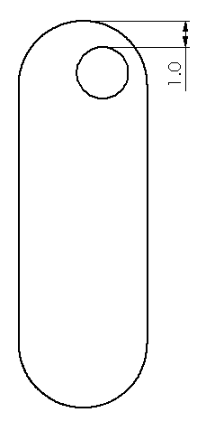
 
OP - what reason makes you not want to add a second dimension to have a full Cartesian (x/y) dim scheme and instead rely on implied parallelism/perpendicularity control or consider adding form control with position or profile? This design is simple and two dimensions will lock the hole position with no ambiguity. What am I missing? Certainly, one dimension does work but you either are relying on implied form control or go through the effort to define it explicitly. Use two dimensions and you are done. If the overall width of the part is highly variable and only the edge distance for the hole to the outer arc is important then your single dim schema and additional specifications makes sense and provides fabrication flexibility.
 
You do not need a datum structure to specify this dimension. It is shown and assumed to be a vertical dimension and only a tolerance is required.
Unless this is a feature whose horizontal location is important or is not addressed in some manner elsewhere, providing a datum structure is overkill.

"Know the rules well, so you can break them effectively."
-Dalai Lama XIV
 
Hi, MattEdwards:

Is there a functional requirement for this 1.0 dimension? If not, then you just need dimensions to locate center of the hole. If you worry about strength of this part, then you need to control min. wall thickness.

Best regards,
Alex
 
Use LMC if you care about wall thickness.
If I were you I'd design a gauge for this requirement. No tricks needed in measurement.
This orientation is not caliper friendly either.
 
I'm not concerned by min. wall thickness or strength of the part; the 1.0 dimension has a functional requirement as it defines the fit of the part in an assembly. The horizontal location is not particularly important so is controlled by the loose general tolerances.

Wuzhee said:
If I were you I'd design a gauge for this requirement
Wouldn't a gauge require that the part has at least one datum to orient the part within the gauge?
 
ewh said:
You do not need a datum structure to specify this dimension. It is shown and assumed to be a vertical dimension

Saying that implies that you already have a datum invoked to establish what "vertical" even means. So I maintain that some sort of datum is still needed.
 
The only definition in ASME Y14.5 for a directly toleranced linear dimension is as a size dimension, which arguably may invoke the distance between opposed points (actual local size) and that's not the intent here. The actual intent may be sort-of clear intuitively to most, but doesn't obligate cotractualy to anything specific unless an explicit and precise clarification of the measurement direction is added as note on the drawing (and by precise I mean that "vertical" is not good enough).
 
Burunduk said:
The only definition in ASME Y14.5 for a directly toleranced linear dimension is as a size dimension
Not quite -- I already mentioned paragraph 4.6.1 above. The stipulation, however, is that those linear/coordinate dimensions be somehow tied back to datums ("mutually perpendicular planes").

That's why I mentioned the use of a note for explicit and precise clarification.
 
Garland, paragraph 4.6.1 is not about directly toleranced dimensions. What the standard refers to by "rectangular coordinate dimensioning" in that paragraph is a method of giving linear dimensions in two coordinate directions to define the location of features, as shown in figures such as 4-47 (there is also "polar coordinate dimensioning" where you give radial distances and angle dimensions to define the location of features as outlined in 4.6.4 and shown in fig. 4-50). These paragraphs and figures don't address any tolerance definition, they address dimensioning only. Since these are location dimensions they are definitely meant to be basic and define the true positions of the holes, as anywhere in the standard where the tolerancing of similar cases is shown.

You are probably confusing it with "coordinate tolerancing", a term many use to describe the "traditional" method in which directly toleranced (plus and minus or limits) dimensions were used for everything including the location of features. This term however is not used in ASME Y14.5.
 
In an old version of Y14.5 from 1994, there was a note in para. 4.4 that said this:

"NOTE: When it is necessary to relate linear and angular dimensions to a datum reference frame, the desired order of precedence may be indicated by a note such as: UNLESS OTHERWISE SPECIFIED, DIMENSIONS ARE RELATED TO DATUM A (PRIMARY), DATUM B (SECONDARY), AND DATUM C (TERTIARY). This note is not to be used in lieu of indicating datum references in a feature control frame for geometric tolerancing applications."

While I think I understand why the committee stopped showing the note in next versions of the standard, I've been in situations where it turned out to be very useful.
 
pmarc,
I've been in similar situations too.
Also as you probably know, the standard for castings Y14.8 kept supporting this method after it was omitted from Y14.5, at least up to the 2009 version of Y14.8. Not sure about the latest one as I don't have it.
 
Essentially this is trying to control an offset between two tangent planes where the offset between the planes varies depending on the orientation of the part.

That orientation is implied by the picture; it's not explicit. Normally that would not be a big problem but there is a relatively large horizontal offset, so that the sine component to variation that would usually be small, isn't.

While there can be datum features identified to make the orientation explicit, the committee wiped out the ability to put a direct distance tolerance on a tangent plane and did not create an option to add one via a geometric characteristic.

Worse, the tangent for the hole should not be based on the as-machined hole, it should be defined from the nominal mating part so that small irregularities that the mating part won't fit into are not considered.

Example, the part could be clamped to two, mutually orthogonal, precision angle blocks and the round end set onto the top of a surface plate. Then this measurement would be made by finding the lowest spot in the hole using a height gauge and dial indicator. If the probe on the dial indicator is smaller than the mating part and the hole is tri-lobed or oval, then the probe could reach a lower place than the mating part can, accepting a part that is not usable.

The standard is not big on construction features to control tolerances on features, just for construction datum reference stand-ins. Ah, well, maybe the 2030 version or naah?

Notes can do this.
 
Status
Not open for further replies.
Back
Top