Eng-Tips is the largest engineering community on the Internet

Intelligent Work Forums for Engineering Professionals

Spider Gang Cultivator Caster Design 2

Status
Not open for further replies.

Lonjevity Farms

Agricultural
Jan 2, 2017
10
0
0
US
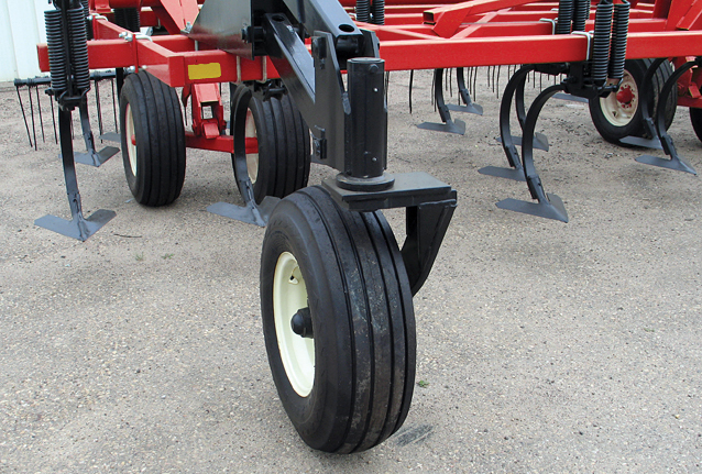
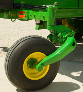
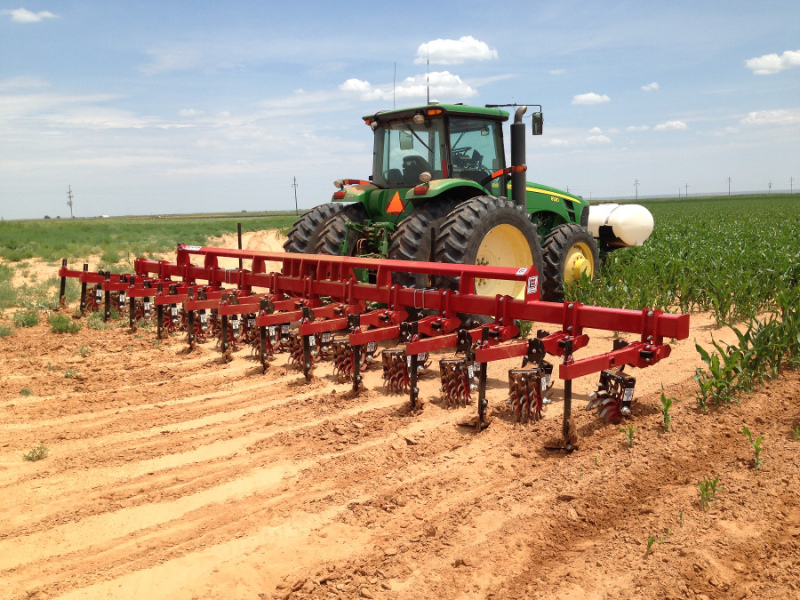
Hello forum, I posted this in the Agricultural forum but it seems nothing ever gets posted there. I am working to improve our 3 point spider cultivator and want to weld up a pair of casters to mount on it. The implement weighs approximately 3000 lbs. and mounts to the 3 point hitch of our tractor. I have the arm design worked out but wanted some input on the pivot section. Looking at zero turn mower pivot tubes as an example, they typically use bushings and/or bearing combinations. Do you think that this product would work with a 1 1/4" shaft pressed fit into schedule 80 tube? These bushings have quite a large dynamic load capacity.

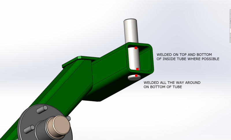
I have attached a few pics of the design from Solidworks. The square tubing is 3 x 3 x 1/4 wall A36 and the shaft is 1 1/4" CR 1020 steel. The pivot tube is X Strong Sch 80 1 1/2" x 1 3/4" long pipe to press the bushings and shaft into. The shaft has a 1/2-20 tapped end for the bolt to apply the necessary preload. The shaft is welded to the square tube via a through hole. The hub and spindle are rated for 1750lbs, two casters total 3500 lbs capacity. Not being familiar with typical tapered roller bearing applications do manufacturers machine out the pivot tube for the bearings or use stock material and press fit?

I could also use these as well but there is significant price difference versus the bushings. Also from a maintenance point the bushings seem a better fit.


caster_2_wg4lzd.jpg

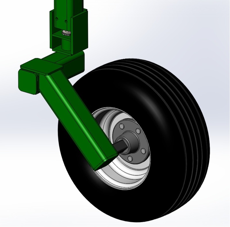
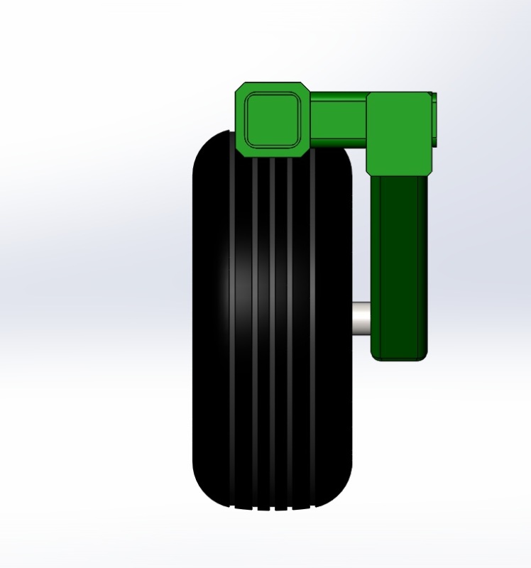
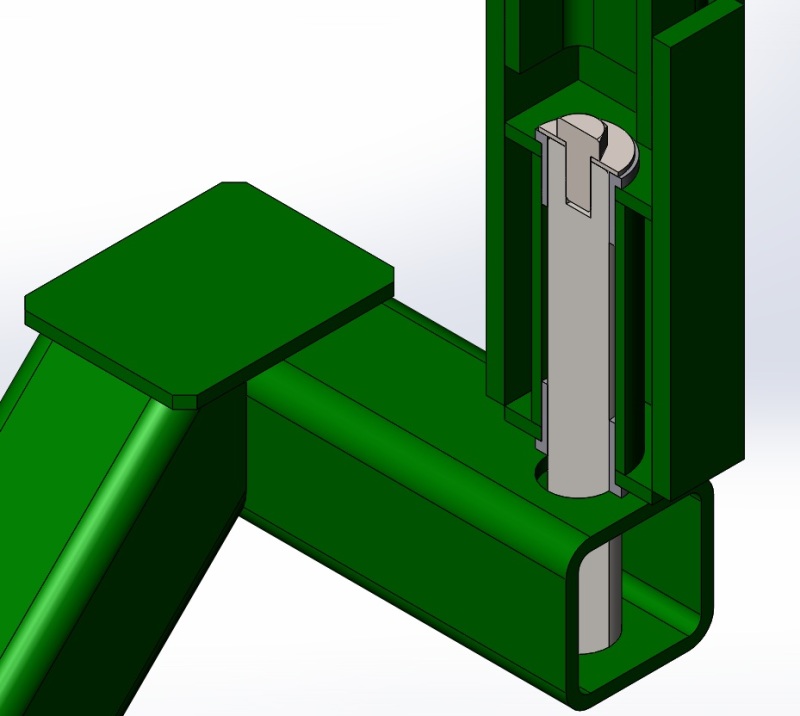
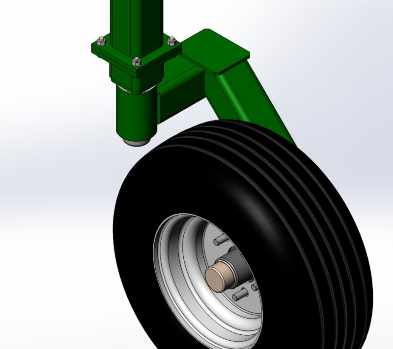
Overview image of caster design
caster_1_bvyb5h.jpg

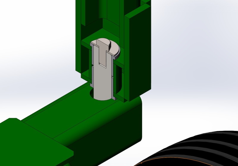
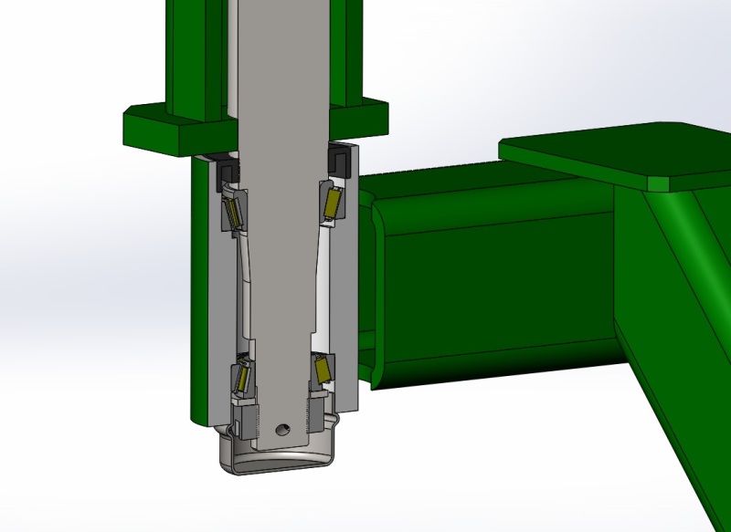
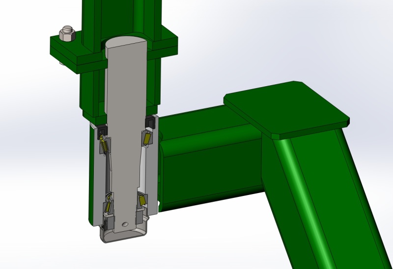
Cross section of end bolt, shaft, pivot tube, and bushings; one on top and one on bottom.
caster_3_nxt5wj.jpg

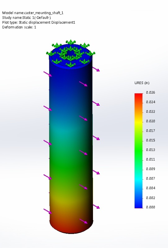
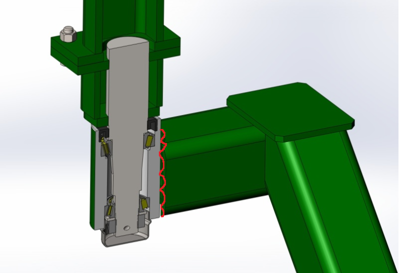
FEM of caster shaft showing displacement. von Mises stress is well within FOS.

Thank you for any suggestions or information.
 
Replies continue below

Recommended for you

Eyeballing it, your swivel looks WAY too delicate.

Note that the wheel load X distance from the swivel axis to the tire contact patch puts a huge moment on the swivel. Two bushings adjacent to one another will each see a force greatly magnified from the load on the wheel.

Take a look at a typical 3000# caster; the swivel comprises a pair of tapered roller bearings spaced some distance apart. The lower one is typically much larger than the upper one. Both are typically much larger than the one you have identified from Macarco.

Another possibility for the swivel is the stub axle sold for travel trailers, which typically has two ball or tapered roller bearings of about the size you have identified, spaced pretty far apart, another way to deal with a large moment.

You can't press any bearing directly into any as-supplied pipe or tube of any size; one or both parts will fail soon. You need to bore and ream the pipe, probably to a tolerance of a couple of ten-thousandths of in inch. The fat end of the bearing's cup also needs a thrust surface on which to bear, pretty damn square to the bore. You need to study the thick 'engineering' portion of a Timken catalog or equivalent.


Mike Halloran
Pembroke Pines, FL, USA
 
Hello Mr. Halloran and thank you for the quick reply. I had considered using a spindle as the shaft in the pivot tube as I used on the wheel. That still leaves me some way to weld a "make shift hub" into the vertical support tube". What would you suggest to use as the "hub" and from what stock could this be made from without a huge expense? I suggested x strong pipe with a 1/4" wall as a stock material to have turned down a few 1/1000 for the bushings above. If I was to use the bearings I would need a much larger "hub" to house the bearings. I have found a few examples on google images of what I am trying to mimic.

Casters way bigger than what I need. But you see the designs.
cultivator-L-caster-lb_g3zwwa.jpg

rear-wheel-D4501_xzfcap.jpg


Thanks for your time in my review.
 
If the pivot point is not rotating frequently, i prefer to use bushing, otherwise it is better to use bearing.
How does the bottom portion (square tube) of the pivot pin is secured?

R.Efendy
 
BEMPE16524, Thanks for the reply. The caster does not really spin much, not like a rotating shaft that spins at 250 rpm. This is just a large version of a zero turn front caster with a one sided fork. The pivot shaft is welded to the square tube on the bottom face as well as the inside top and bottom face where accessible.

Shaft welded to square tube horizontal arm.
caster_4_serebw.jpg


Thanks for any insights.
 
I think you should add some sort of greasing point on the bushing side.
Besides helping the movement, it will help you a lot during maintenance when you need to disassemble the parts.

R.Efendy
 
Beside the caster mounting shaft being questionable in size, I believe that you may not have adequate bearing surface contacting the caster mounting shaft which in due time you will see compacted holes and cracked welds. You would not need to increase the wall thickness in that portion of the square tubing. The welding around the shaft on top of the square tubing will also interfere with the assembly,shown as a cross section, above that tubing. You may also double check on the wall thickness of the square tube where the square shaft is attached. Agricultural land surfaces can be rough on equipment, so I would expect 3000lbs load from wheels can be significantly magnified.
 
The two pictures you have attached of other designs should be highly informative for you- notice that in both of them the pin/bushing set is much taller that your arrangement is. This is to counteract the large moment that MikeHalloran is talking about.

Also notice that in both cases, the centerline of the pin/bushing assembly is closer to the centerline of the wheel than in your arrangement- this also reduces the moment applied to the pin/bushing assembly.

Also notice that in both cases, the load path from the wheel, through the pin/bushing pair, into the structure passes through relatively thick sections with long, simple welds (or cast parts in the case of the Deere arrangment) which keeps the loads in the welds low.

That first arrangement is very simple and to my eye looks like a very robust and easy to disassemble/maintain way to solve this problem. If I were in your shoes I would copy it closely, sized for the load you need.

Not sure what type of loads you are applying in your FEA- but make sure to account for impact loading, not just static and operating loads. Your assembly is not sprung, which means when your caster hits a rock or stump or whatever, the load into the bushing, pin, and structural attachments thereof has the possibility of spiking to a very high number.
 
Lonjevity Farms,
One other thing I notice, and I do not know if it is important in your design . Do you have any means of shimmy damping ?
some types of farm machinery have a friction damper in the caster shaft.
B.E.

You are judged not by what you know, but by what you can do.
 
Thank you everyone for all your expertise and recommendations, I believe these forums are an invaluable tool. jgKRI to answer a few questions. The center line of the pivot shaft and wheel are directly collinear or in line with each other.

See this top view.
top_view_caster_dnm4d7.jpg


As far as the FEA analysis, that was done with a 7000lbs static load with the radial load distributed on the whole shaft with the end fixed. I am currently learning how to do impact loading using Solidworks which is, as far as the Solidworks FEA is concerned, done using nonlinear dynamic analysis.

I have decided on the following course of action. We have two identical spider gangs.

1. Build and put two casters on one machine with this updated design (from your recommendations). This design uses a standard 1750lbs stub spindle, bearings, grease seal and dust cap. The hub is being turned on a cnc lathe at a local machine shop. The hub is welded to the square tube.

bearing_hub_1_skevnc.jpg


2. Build and put two casters on another machine using the original design with the bushings but with an extended distance between the bushings as recommended by BEMPE16524 and chicopee. The design uses the bushings and like Mr. Mike said the XX Strong Sch 80 pipe is bored and reamed by the same shop turning the hubs.

caster_bushings_1_vk9pfh.jpg


Thanks again for all your input. I will post additional pictures when they are installed.
 
Lonjevity Farms,

jgKRI was likely referring to the "trail" of the caster, the distance between the caster pivot axis and the wheel rotational axis. Your overhead view shows this non zero distance. Of course, it should be non zero. I believe jgKRI's point is that it should be minimized within certain bounds.
 
Mr. Nescius,

Thanks for clarifying that for me. I am not that familiar with caster vernacular. I found this image and read about the caster trail and now I understand it. I kept the angle at 45 degrees like the JD to help with the height of the assembly and to be able to use a tire of sufficient load capacity. The tire height and the implement height was the constraining aspects of the project. I am also trying use steel sections and scrap we have around the farm.

caster_trail_hvwhbb.jpg


Here is a picture of a Lilliston spider cultivator. Ours is not this big and is another brand.

bigham_spider_nnjksn.jpg


Again thanks for your input.

Tom
 
"Trying to use scrap we have around the farm". Think this sums up nicely the importance of the whole exercise.

It is a capital mistake to theorise before one has data. Insensibly one begins to twist facts to suit theories, instead of theories to suit facts. (Sherlock Holmes - A Scandal in Bohemia.)
 
Nescius said:
jgKRI was likely referring to the "trail" of the caster, the distance between the caster pivot axis and the wheel rotational axis. Your overhead view shows this non zero distance. Of course, it should be non zero. I believe jgKRI's point is that it should be minimized within certain bounds.

Yes, I was referring to trail.

Lonjevity Farms:

In the picture you posted, 'castor trail' is what I was talking about as Nescius explained.

Your first explanation, that the center line of the wheel is in line with the pivot axis, is also important but I assumed you understood this (as you clearly do).

The trail dimension does two things- both relatively simple and intuitive. One: the longer the trail is, the higher the apparent force keeping the tire parallel to the direction of travel of the pivot. This is a good thing. Two: the longer the trail is, the higher the moment put into the pivot system by the wheel loading. This is not good or bad, it just needs to be accounted for.

With that said, my engineering brain likes both details you have come up with. My suspicion is that the arrangement with roller bearings is substantially more expensive, but it looks like it will be very robust in all directions.

The only thing I would check on that design- when moment is applied to the stub shaft, it has to transfer that moment back into the structure (as we've talked about a few different ways). The weld at the bottom will almost certainly not be strong enough to handle this on its own. There needs to be some reinforcement at the opposite end of the stub shaft (similar to your gusset/weld arrangement on the top end of the design using bushings). The further you can get that connection from the bearings, the more robust the assembly will be.

I'm assuming you know this already and have some detail to anchor the top end of the stub shaft, but thought I'd bring it up just to make sure.
 
I see a problem with the machined surfaces for the roller bearings and seal being exposed to the heat and deformation of the welding of the hub to the square tube.

"God will not look you over for medals, degrees or diplomas, but for scars." - Elbert Hubbard
 
Lnewqban said:
I see a problem with the machined surfaces for the roller bearings and seal being exposed to the heat and deformation of the welding of the hub to the square tube.

That's legitimate, but personally I wouldn't be THAT worried about it. This isn't a high speed rotating assembly. As long as the bearings fit after welding, the assembly will function as intended.
 
I second that gussets are added for strength. but far as the welds go, I be concern of the welds cracking if not done properly. and will fail.
why not add a solid piece were the pin is shown to be welded. weld the solid part to the square tubing , have a hole straight thru. shrink fit
the pin into the hole with a solid flange. then weld the top of the square part to the pin. making it more robust and rigid.. ...
 
jgKRI,

I have modified the caster so the spindle is to be welded and supported on both ends as you and mfgenggear suggested. The mid section is bolted to the support leg. This will allow replacement of the spindle section when it wears without having to manufacture another support leg. The mid section is just a piece of tube welded to the top and bottom plate with holes to accommodate the spindle for welding.

Lnewqban,

As far as the heat on the spindle from welding, don't trailer companies weld the spindles into round and square tube for the axles with no problems with bearing fitment?

Section view of middle section bolted to support leg

bearing_hub_2_vx9ryb.jpg


Iso view of caster.

bearing_hub_3_djl3w2.jpg


Link to download the solidworks viewer if anyone wants to view native files. I can email them upon request.
 
Lonjevity Farms said:
As far as the heat on the spindle from welding, don't trailer companies weld the spindles into round and square tube for the axles with no problems with bearing fitment?

Yes- the spindle can be welded all sorts of ways without much problem, because any welding you'd be likely to do to create an axle would involve a weld that is symmetrical around the long axis of the spindle, meaning it probably won't distort much.

What he's talking about (I think..) is not the spindle attachment, but the hub. Shown below in red.

Untitled_oxzc5x.png


That weld is going to tend to distort the bearing mounting surfaces, pulling the bores out of round.

As I said, in my opinion this is not of major concern because this assembly isn't going to rotate around that spindle at high speed. In something like a trailer or other system where the spindle is spinning at a few hundred or thousand RPM, bearing alignment is really important and it's crucial that the bearing surfaces are all accurately machined and aligned well.

This application loads the bearings in a static condition. This means that bearing seating bore distortion is only a problem if it is REALLY bad.

You can protect against this problem by selecting bearings which will tolerate a little bit of misalignment, just in case the hub body distorts when it is welded.

The other way to do it would be to machine the bearing surfaces in the bore after the assembly is already welded together- but this changes the operation from one which can be done easily on a lathe, to one which likely requires very precise work on a mill- meaning it's a cost adder. For this application I do not believe you need that level of precision.
 
Status
Not open for further replies.
Back
Top