KevinW1266
Mechanical
Good afternoon all,
I'm learning a bit more about the streamline drive for contour milling, and have a question about why my first pass is penetrating the part so much. I'm working on making a toolpath for an incremental forming operation, and to do so I have created a geometry which is the "negative" of the shape I'd like to form, think of it as what you would use as a die if this were a conventional stamping operation, and then specified that the blank is just an offset of 0.150". With this workpiece, and a half inch ball mill tool, I am then trying to mill away this excess from the part wall surface (which will in turn output the toolpath that I need for my blunt tool to do the incremental forming).
I have two issues however that are coming up:
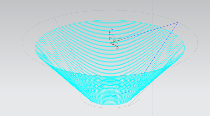
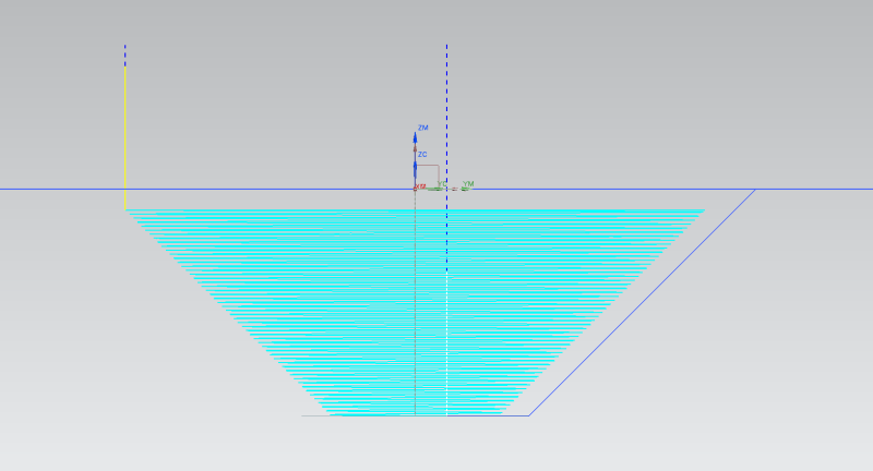
1) The toolpath, when generated, outputs a spiral with the pitch that I am looking for, but the first step is a plunge of roughly 3 times the pitch. I have tinkered around and found that the first step that the software puts in is roughly 1/4 of the tool diameter, which I can then work around by changing the diameter of my part to be formed, but this is quite the hassle. Is there a setting that I am missing which is causing this first jump to be so great? I've added photos below which illustrate this phenomenon also.


2) When all is said and done I post process the toolpath with the canned 3 axis mill (or 3 axis mill TURBO which gives the same problem) and the output G-Code is VERY long. I've cycled through using "Line", "Arc - Parallel to Axis", "Arc - Parallel/Perp to Axis", and even "Nurbs", but each of them give me G-Code that is so long that the CNC controller we use in my lab cannot accept it in a single program. Am I missing something blatantly obvious, or is this just something I'll have to work around as well? I could write a G-Code to do what I want in about 10 lines I think using G2.1 or G3.1 commands, but the program doesn't seem to use these?
Anyway, thanks for any and all help you guys and gals might be able to offer me, and have a great day.
-Kevin
I'm learning a bit more about the streamline drive for contour milling, and have a question about why my first pass is penetrating the part so much. I'm working on making a toolpath for an incremental forming operation, and to do so I have created a geometry which is the "negative" of the shape I'd like to form, think of it as what you would use as a die if this were a conventional stamping operation, and then specified that the blank is just an offset of 0.150". With this workpiece, and a half inch ball mill tool, I am then trying to mill away this excess from the part wall surface (which will in turn output the toolpath that I need for my blunt tool to do the incremental forming).
I have two issues however that are coming up:
1) The toolpath, when generated, outputs a spiral with the pitch that I am looking for, but the first step is a plunge of roughly 3 times the pitch. I have tinkered around and found that the first step that the software puts in is roughly 1/4 of the tool diameter, which I can then work around by changing the diameter of my part to be formed, but this is quite the hassle. Is there a setting that I am missing which is causing this first jump to be so great? I've added photos below which illustrate this phenomenon also.


2) When all is said and done I post process the toolpath with the canned 3 axis mill (or 3 axis mill TURBO which gives the same problem) and the output G-Code is VERY long. I've cycled through using "Line", "Arc - Parallel to Axis", "Arc - Parallel/Perp to Axis", and even "Nurbs", but each of them give me G-Code that is so long that the CNC controller we use in my lab cannot accept it in a single program. Am I missing something blatantly obvious, or is this just something I'll have to work around as well? I could write a G-Code to do what I want in about 10 lines I think using G2.1 or G3.1 commands, but the program doesn't seem to use these?
Anyway, thanks for any and all help you guys and gals might be able to offer me, and have a great day.
-Kevin
