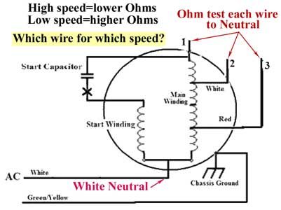
I picked up an old GE 5KCP19 motor and it has a five wire connection. Metering the leads, the continuity values are as follows.
Bk-Wht. 0
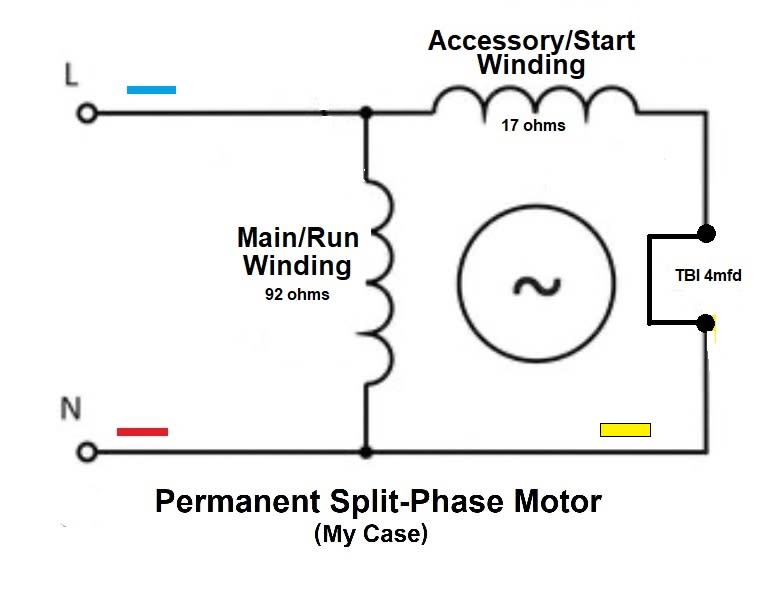
Bk & Wht-Red 92
Yel-Blu 17
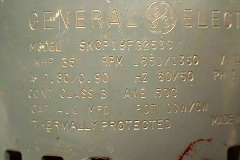
Motor Ratings…
115V, 1650/1350 RPM, 35 Mhp, Cap 4Mfd. CW/CCW
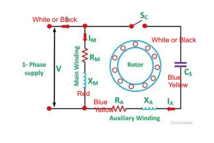
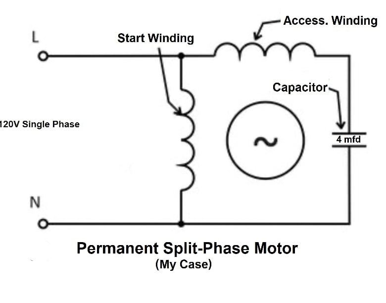
Would appreciate connection help (simple diagram) so I can use it.
Thanks!
Bk-Wht. 0
Bk & Wht-Red 92
Yel-Blu 17
Motor Ratings…
115V, 1650/1350 RPM, 35 Mhp, Cap 4Mfd. CW/CCW
Would appreciate connection help (simple diagram) so I can use it.
Thanks!