Continue to Site

Eng-Tips is the largest engineering community on the Internet

Intelligent Work Forums for Engineering Professionals

  • Congratulations KootK on being selected by the Eng-Tips community for having the most helpful posts in the forums last week. Way to Go!

Square shaft design 5

Status
Not open for further replies.

dejan95

Mechanical
Aug 24, 2020
60
Hello everybody,

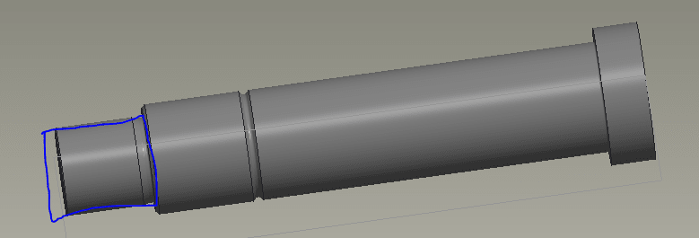
I have a question about designing a square shaft. Picture bellows shows my shaft which is round. At the end (t highlighted part) I would like to make it squere to prevend turning of the part that is attached to it. (unfortunately I don't have enough room for a dowel or a pin).

So this part would probably be made with milling? How do I design it so the operator won't have any problem making this part.

Capture_xoduoy.png


Thank you in advance!
 
Replies continue below

Recommended for you

Hi dejan95

You can hold the workpiece in a three jaw or four jaw Chuck, however you don’t have to make it fully square, if you mill two flats on diameter that should be sufficient to stop it turning when assembled but if you need it square you can just hold it in the Chuck I mentioned above.

“Do not worry about your problems with mathematics, I assure you mine are far greater.” Albert Einstein
 
@desertfox

Thank you. That's what i thought.

I have on additional question. If i make it with a key, can I make a hub keyway only to the next surface (not all the way through)? Becouse as you can see on the picture bellow I would only need a keyway for 10mm and than there is another different diameter for clearance hole for a screw.

Capture2_m2ywcw.png
 
if it is a small shaft (for instance an electrical appliance used in kitchen) you can do only one mill
shaft_qre5bt.jpg
 
Hi dejan95

Yes it’s possible to have a blind keyway in the hub but machining them is a lot more difficult, if you go down that route you need to calculate the torque capacity of the key and keyway based on the shortest engagement.

“Do not worry about your problems with mathematics, I assure you mine are far greater.” Albert Einstein
 
@desertfox and @robyengIT thank you for your help.

Best regards!
 
instead of flats, what about a pair of dowel pins, or if the load is small, a single off-axis pin ?

another day in paradise, or is paradise one day closer ?
 
First, a compliment! You did the right thing by asking how your part would be made. Too many engineers never do that. They end up designing parts that cost much more than they should, if they are even possible to make. In one of my first jobs, I remember a cohort designed a part with a square hole. A square hole is very easy to draw. He got into a shouting match with the shop guys. "Why do you need a square hole?" His only defense was "Make it that way because that's the way I drew it". He didn't need a square hole but he would never admit that. He didn't last long.

You have been given good advice above. I would add one more tip - try to talk to and learn from the people that have to make your part. I have been designing machines for decades, but I never once took a machine shop course. I have deeply regretted that many times. Over the years I have spent a lot of time talking to and learning from accomplished machinists.

Make it a habit to spend LOTS of time with the guys making your parts. You'll learn very helpful tips, concepts, and error sources. You'll get a feel for what equipment, setups, and fixtures are required. You'll better understand the true cost of tolerances and finishes you may be asking for. And even potential sources of errors. For example, my standard inch dimensioning is in decimals. One machinist asked me to dimension standard clearance drilled holes in fractions, simply because that's the way his drills were labeled in the box. Makes sense to me, plus we eliminate one potential source of error, his decimal/fraction conversion. I don't dimension all holes that way, just the ones that can withstand that level of tolerance.

The other BIG benefit of spending time with them is that they will know you value their opinion. As such they will be on your team. Instead of bitching and moaning about how stupid that engineer is they will feel free to call you and ask about something they see on a drawing. The net result is that your parts will cost less and work better.

Keep asking!
 
dejan95

a better understanding of what this assembly does and the precision required, and torque required.
there many ways to assemble the two details. does it have to transmit torque? and what are the requirements.
starting point is what RPM and torque required.
a groove behind both details will enhance machining on both details. a square or d hole will require a punch or pull broach.
blind hole will limit to punch or edm.
how precise does both details need to be assembled.
 
The two flats recommendation is good, but you could take it a step further depending on torque requirements. D-shaped shafts are very common. A singe flat eliminates the need for indexing the flat on an otherwise round part.

If you do need to make it square, a collet in a square collet block is your easiest/cheapest bet, but an indexing head would also make short work of it.

Collet block example:

To use the collet block, you chuck your part in it and simply spin the collet block with the part in it in your mill vise to make each flat. In your case, I would look for one like in the link above that tightens with a ring at the front, so that you can push your part all the way through it and machine on the 'back' side of the collet rather than trying to chuck up on that shoulder on the other end of your part and having most of the part sticking out free (Though you could do the latter if you setup so that the stickout is supported on vblocks or similar, and only used the collet for it's index). Some collet blocks use a draw type tightening mechanism that would preclude sticking the part all the way through to the back side.
 
D-shaped shafts are indeed very common. And also one of the most common failures. They are common because they are easy (read cheap) to make. They fail because matching D-shaped bores are very difficult to make, so engineers commonly just use standard round bores and use a set screw to engage the flat and (supposedly) lock the bore to the shaft. A set screw will eventually wear out a divot on the shaft, thus enabling free-play. It shifts every time the torque reverses, just making the divot larger and larger. Eventually it slips and fails. Maintenance guys hate to see D-shaped shafts because they know they will be repairing or replacing them at some point. Making a D-Shaped bore that engages the shaft with the proper clearances can be done but not very easily. A flat is a lousy way to transmit torque.

Everything above also goes for double-flatted shafts.

I personally just consider the whole flatted shaft thing a lazy way to design anything. I'm sure many will disagree and have evidence of past successes. But this remains my opinion.

Is there any good reason you couldn't just go with a standard cylindrical keyed shaft and bore?
 
All valid points!

To follow up on MintJulep's train of thought, if it doesn't need to come apart again, there's loads of geartrains out there where the gears are shrunk fit to shafts without any other retaining feature, and even simpler, loctite makes some really foolproof retaining compounds meant for the purpose. If the assembly doesn't have a high upper temperature limit, the retaining compound could be chosen such that simply heating the assembly with a torch allows for the assembly to be disassembled (Also assuming the parts are all metal).

Cheers,
Nathan
 
Hello,

How much torque is being transmitted? This might provide some guidance for selecting a shaft shape along with the mating component. We have a small capstan drive that uses a DC motor with a D shaft mated to a spool that has a D cutout created by wire EDM. As JBOGGS mentioned, putting a D shaft into a round hole can invite trouble. In fact, many years ago our spool had a round hole which required us to use a set screw and cross pin the spool to the shaft. Changing to a D hole solved the problem.

If you choose a square shaft, you have some options on making the cutout in the mating part. Check into broaching, EDM and rotary broaching. Rotary broaching is interesting because you can "drill" a square hole.


Kyle
 
The mere existence of a square feature might add slightly to the cost of the part but its not overly complex by any means and easily manufactured. If that is a low-volume part then you're likely wasting more money debating shapes than making it square.

JMO but I am extremely surprised by several of the answers given above. Keys, set screws, and flats are generally not used as drive features in rotating machinery by competent engineers but simply for indexing the shaft relative to the mating part. The reason for this should be obvious - bc you're creating a weak joint. Typically the driving feature is either a taper or shoulder on the shaft with a bolted joint compressing the two parts together, or a split clamped coupling.
 
I use to observe in the past double d and single d through holes with a simple gear. not very much on new designs, d & double d holes are a pita, reason normally can only be broached.
and when a tight diameter has to be held, seen very few square holes in my line of work. mostly splined holes. and some keyways.
if it's very low torque requirement a keyway is fine. they use it on small engines with a magneto. only with centrifugal force. I would rather use a keyway than a square hole.
and if more torque required a splined hole.
 
It is understood that only manufacturing is the problem. But if a round shaft is machined to a square shape the torsional shear stress increases non-linearly with the same torsional moment. This should also be looked into.
 
Status
Not open for further replies.

Part and Inventory Search

Sponsor