Continue to Site

Eng-Tips is the largest engineering community on the Internet

Intelligent Work Forums for Engineering Professionals

  • Congratulations KootK on being selected by the Eng-Tips community for having the most helpful posts in the forums last week. Way to Go!

Square size callout position 1

Status
Not open for further replies.

sendithard

Industrial
Aug 26, 2021
166
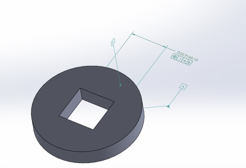
I've got this square callout for size then a position for said size.....I still don't remember much from the standard on this square drive symbol.

I measure both linear sizes independently and both positions independently. Seems simple and to the point. I measure both opposing planes as a planar position.

I've got an engineer asking me to output this as a normal hole-like position...asking me to create an axis b/w both midplanes and then a position callout.

Doesn't seem like acrazy request, but I'm curious your thoughts.

SQUARE_DRIVE_p7rlbg.jpg
 
Replies continue below

Recommended for you

Is there a functional reason they want it that way?
The only case in which I would consider requiring control of a square hole by axis position is when it constrains a round shaft at the assembly.
Then it is possible to treat it as type (b) irregular, type (a) feature of size for being able to contain a cylindrical AME. This should be dimensioned in a way that reflects the design intent and a diametrical tolerance zone should be used for position. Not sure your CAD where you do the 3D annotation will support it.
 
Little workaround: drop the square symbol and dimension both width with their own position FCF.

I liked the square symbol because it made the drawing look "professional" then I completely dropped it because we always ran into lengthy debates.

See this article about square symbol.
thread1103-512776

 
Status
Not open for further replies.

Part and Inventory Search

Sponsor