Continue to Site

Eng-Tips is the largest engineering community on the Internet

Intelligent Work Forums for Engineering Professionals

  • Congratulations SDETERS on being selected by the Eng-Tips community for having the most helpful posts in the forums last week. Way to Go!

Stackup calculations (X min / X max.) 3

Status
Not open for further replies.
Replies continue below

Recommended for you

MIN = 2.5 mm
MAX = 6.05 mm

John-Paul Belanger
Certified Sr. GD&T Professional
Geometric Learning Systems
 
J-P,

If I am not mistaken, your numbers have been calculated with the assumption that LMB size of the datum feature A is 19.0. Are you sure it is the correct value?

Thanks
 
What else would the LMB be on an external diameter? There is no datum referenced in the FCF ahead of A.

John-Paul Belanger
Certified Sr. GD&T Professional
Geometric Learning Systems
 
Pmarc,
Should we use 18.5mm as the LMB size for datum feature A?
Also please correct me/educate me if I am wrong, perfect form at MMC is still needed for the OD and perfect form at LMC is only mandatory for the ID?

What are your x min and x max values?
 
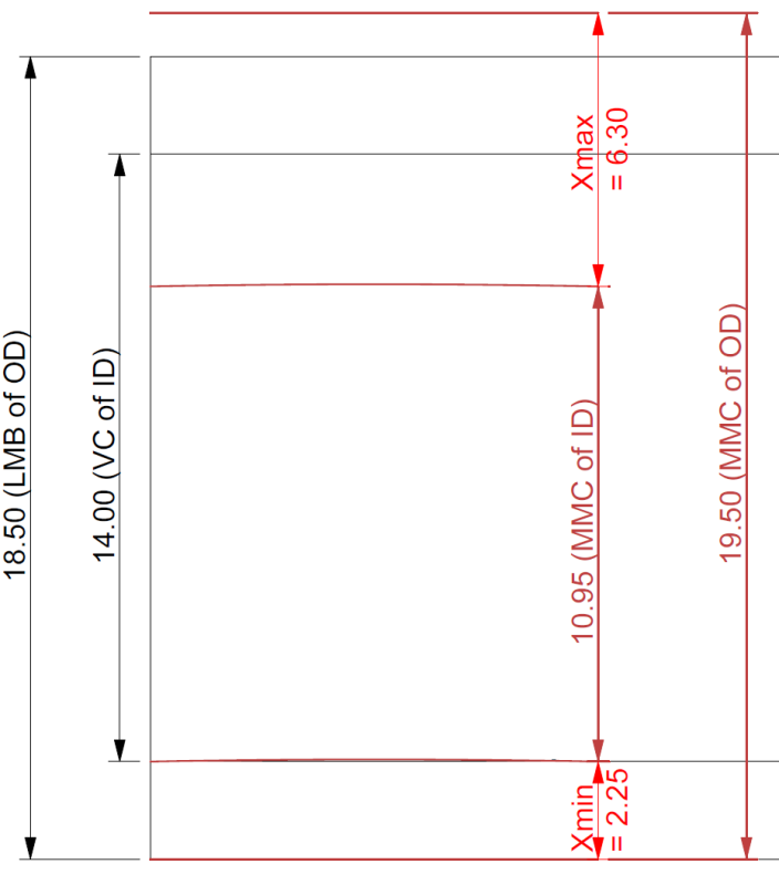
I agree with greenimi. Datum feature A is only controlled by a size tolerance, and is subject to Rule #1 (perfect form boundary at MMC). It could have an actual local size of 19, and be bent by 0.5. The LMB, or the maximum inscribed cylinder, would be 18.5. This makes the extreme wall thickness values 2.35 and 6.3.

Evan Janeshewski

Axymetrix Quality Engineering Inc.
 
I like the way 2.7.1 (c) is worded: Where is no default requirement for a boundary of perfect form at LMC.
 
Yes, but the question is the max and min "X" -- which I assumed means the consistent wall thickness. I think you guys are referring to the wall thickness at a cross-section ... would that have something to do with why we get different answers?

John-Paul Belanger
Certified Sr. GD&T Professional
Geometric Learning Systems
 
greenimi,
My answer to your first two questions is yes.

My numbers in the third question are 2.25 for Xmin and 6.3 for Xmax.

J-P,
For the consistent wall thickness the answer is the same as for the wall thickness at a cross section.
 
Sounds good -- I should have sketched it all out before plunking down the numbers!

John-Paul Belanger
Certified Sr. GD&T Professional
Geometric Learning Systems
 
To get the 6.3 wall thickness value**:

{ LMC OD 19
+ 3 * OD_TOL 0.5
- LMC ID 11
+ LMC Pos Tol 3.0
- 2 * ID_TOL -0.05}
/ 2

To get the 2.25 wall thickness value:

{ LMC OD 19
- OD_TOL 0.5 (<- This is from adding 0.5 to get the MMC condition,
then moving a direct -0.5 from allowable bend/oval into the
diameter-based equation by multiplying by 2.)
- LMC ID 11
- LMC Pos Tol 3.0
+ 0 * ID_TOL -0.05} (<- This is already at LMC; the tolerance moves away from
that boundary and has no contribution.)
/ 2
---------
** That calc is based on figuring how rig the numbers to get the previously mentioned result.

My derivation is as follows:

The diameter of the OD at MMC is 19.5; the LMC diameter is 19.0 so the farthest the datum simulator can travel is 0.5.
The distance from the far outer wall to the offset datum simulator center is 19.5-(19/2) = 10
The distance from the center of the datum simulator to the center of the shifted MMC hole can be (3 + .05)/2
The radius of the hole at MMC is (11 -.05)/2; subtract the shift from the hole -> (8 -.1)/2 = 3.95.
This is the distance from the offset datum simulator center to the far wall of the hole.

Take the difference 10-3.95 = 6.05

or, as above:

{ LMC OD 19
+ 2 * OD_TOL 0.5
- LMC ID 11
+ LMC Pos Tol 3.0
- 2 * ID_TOL -0.05}
/ 2
 
3DDave,

The 6.3 for Xmax was calculated with the assumption that the LMB size of the datum feature A (18.5) is not equal to its LMC size (19.0). If you did the same thing, your derivation would be like this:

The diameter of the OD at MMC is 19.5; the [highlight #EDD400]LMB[/highlight] diameter is [highlight #EDD400]18.5[/highlight] so the farthest the datum simulator can travel is [highlight #EDD400]1.0[/highlight].
The distance from the far outer wall to the offset datum simulator center is 19.5-([highlight #EDD400]18.5[/highlight]/2) = [highlight #EDD400]10.25[/highlight]
The distance from the center of the datum simulator to the center of the shifted MMC hole can be (3 + .05)/2
The radius of the hole at MMC is (11 -.05)/2; subtract the shift from the hole -> (8 -.1)/2 = 3.95.
This is the distance from the offset datum simulator center to the far wall of the hole.

Take the difference [highlight #EDD400]10.25[/highlight]-3.95 = [highlight #EDD400]6.3[/highlight]
 
At least I know what is required to get you to show your work.

What's interesting is that there is no example in the standard of an LMB datum reference that has both an explanation and no other related FCF. Figure 7-17, which is where the question came from, contains no 'means this' section. That's an odd omission considering it's a featured example.
 
pmarc

Its easy to understand MMB, but I am confused at LMB here, may I know how do you get the LMB figure 18.5? Thanks lot.

Season
 
Hi All,

After all that effort, I mistyped one of the values in my previous post - I meant to type 2.25 and not 2.35. No, really, I had it right and didn't have to look at pmarc's calculation ;^).

I used a different method to calculate the result. I sketched the boundaries and an extreme as-produced feature, and then measured the wall thicknesses.

Fig_7-17_Thickness_Calcs_qsms20.png


The black lines are the boundaries and the brown lines are the as-produced part.

3DDave,

I think that they apply a "perfect form at LMC" mindset to the wording in Y14.5. If there is no explanation provided, as in Fig. 7-17, then there can't be any errors. If they say a little bit, as in 2.7.1 (c), then there can be one error as you pointed out. If they say a lot more ...

Evan Janeshewski

Axymetrix Quality Engineering Inc.
 
Seasonlee,

Draw a banana shaped cylinder with section dimension of 19 inside a 19.5 boundary. You lose .5 on each side.
 
axym said:
I meant to type 2.25 and not 2.35. No, really, I had it right and didn't have to look at pmarc's calculation ;^).

Evan,

We believe you…..
For at least two reasons:
1. We know you know this stuff.
2. Pmarc calculations did not include X min (2.25 calculations), but only 6.30 (X max). He included only the final result for X min. (2.25);
 
greenimi,

Thanks. I actually didn't even read pmarc's or 3DDave's derivations in detail. I have a hard time thinking of these things in terms of center geometry and radii - I do much better with diameters, and the surface interpretation. I also need the picture - I can see things in my mind, but only up to a certain level of complexity.

I agree with 3DDave that the lack of a "means this" for Fig. 7-17 is a concern. The only explanation in the text is "allowable displacement results when the datum feature departs from LMB". It appears that Y14.5 didn't think through the implications of a datum feature referenced at LMB, but without a tolerance referencing it at LMC (that would switch the perfect form boundary to LMC, according to the special rule). I don't think that this figure (or its explanation) has been changed in the new draft, so there must not have been many (or perhaps any) comments on it during the review process.

Evan Janeshewski

Axymetrix Quality Engineering Inc.
 
Just to be clear, I have not shown any of my derivations yet - I merely corrected 3DDave's derivation for Xmax and, to be honest, some pieces of it are still a mistery to me :)

For what it is worth, my preferred way of doing stacks is to use A.Krulikowski's method, but I noticed that the method isn't easy when it comes to explaining its logic/mechanics (especially to those who are not familiar with it). That is why in this forum I have always tried to explain my derivations by using additional sketch(es) and bringing the numbers down to simple equations. Here I will make no exception, although in this case the sketch looks pretty similar to Evan's graphic.


Side note #1:
I agree with everything that Evan said about lack of sufficient explanation on how to calculate LMB size for unrelated features of size in current Y14.5. From what I see the figure has been completely removed from the draft of new Y14.5, however there is one statement in the draft that changes the story a little bit, in my opinion. In para. 7.11.8 they say: "When an LMB equal to LMC is the design requirement for a given datum feature, a zero geometric tolerance at LMC is specified to the datum feature [...]". They explain it using an example with secondary and tertiary datum features controlled with 0@LMC geometric tolerances, but that statement stays true for primary (unrelated) datum features too. In other words, if in OP sketch the datum feature A had had a zero straigthness at LMC applied (as a DML control), the LMB of A would have been 19.0. Without it the LMB is 18.5.

Side note #2:
Evan, my sincere apologies for not waiting with my reply until you corrected the typo in your post :)
 
pmarc
Excellent, your sketch illustration always worth a star.

Season
 
Status
Not open for further replies.

Part and Inventory Search

Sponsor