Eng-Tips is the largest engineering community on the Internet

Intelligent Work Forums for Engineering Professionals

Static Electricity creating pulse on ground that is clearing shift register?

Status
Not open for further replies.

Oaklandishh

Mechanical
Sep 3, 2014
48
0
0
US
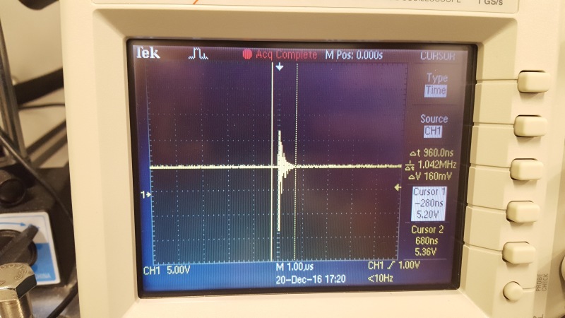
So recently due to the low temperatures and in turn the low humidity I have been seeing this weird thing where if you wiggle too much in a chair near the circuit-board and power system I have been working on, then stand up, you create a pulse in the ground of the system which is strong enough to toggle the clear pin on the boards shift register.

20161220_160210_dbwjtm.jpg


The chair is according to my DMM isolated from the floor, and the person standing up needs only to either zap themselves by touching the chair or sometimes just walk away from the chair in the correct direction to recreate this.

I am not an amazing circuit board designer so I am guessing I made some simple error that anyone with experience would know not to do.

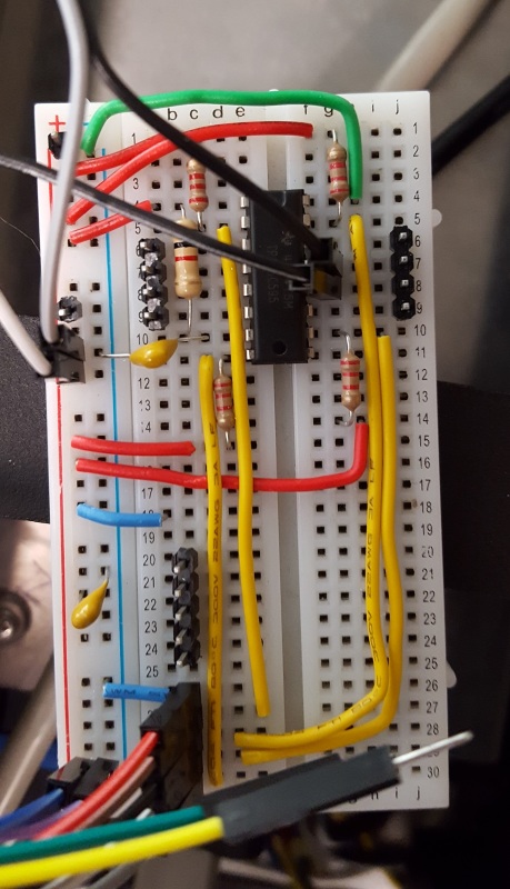
All of my ground planes are connected. They were in a web style connection earlier, but I tried moving the shift register to a point style connection on solder-less breadboard and still had issues.

All of the grounds are also connected to earth ground through the 120VAC 3 prong plug GND as well as the chassis holding everything.

The 120VAC comes in and goes to a switching 24VDC PSU which has negative jumpered to earth ground. That then goes to a motor controller made by ZABER with 4 DO pins and an analogue out with a 5VDC pin which I use to control the shift register.

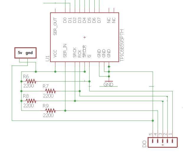
I have tried adding caps between the 5VDC and GND, I have put a resistor and caps between the 5V and CLR pin and CLR pin and GND respectively.

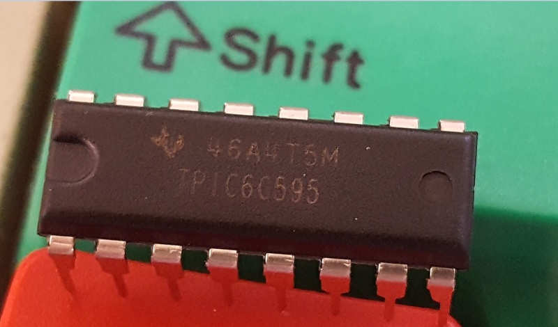
The shift register in question is a TPIC6c595 although I don't think its particularly important to the question.

Any suggestions?

Thanks.

Schematic_Simple_busdqz.png
 
Replies continue below

Recommended for you

Try using an RC filter at the reset input. Place a capacitor between the reset pin of the IC and ground as close to the IC as you can. Then place a resistor in series between the rest ping the off board connector. The biggest issues with static discharges is the high frequency components. Incredibly difficult to track down and eliminate.
 
@VE1BLL Yes. Neither the chair nor the person is touching anything other than each other or the ground which is non-conductive.

@djs I think I had an RC filter at some point as I stated in the original post "I have put a resistor and caps between the 5V and CLR pin and CLR pin and GND respectively.", but I am not completely sure of this because its been a while since I have done low pass filters, I also did not think to hard about what resistor or capacitor I was using. Theoretically I should design it to block things at a frequency range of around 1/600ns or 1.7MHz as that was the length of the pulse?

@BrianE22 by the +5v input pin you mean between the 5v and ground coming into the circuit as shown in the schematic?

Thanks for all the responses so far.
 
oaklandish said:
@BrianE22 by the +5v input pin you mean between the 5v and ground coming into the circuit as shown in the schematic?

Yes, but, the cap should be as close to the device pin as possible. Same as any cap across a reset pin.
 
If you indeed do not have the CLR pin running to the connector and you have it directly tied to the 5V bus with reasonably short traces and the 5V is decoupled at the 595 then this issue has nothing to due with the CLR pin. It is much more likely to be "ground bounce" where the boards entire ground plane is jerking wildly around the 5V and from the 595's point of view probably the entire 595 is being reset.

You need to look at your grounding and how it relates to your development setup and how it's being thrashed by the static discharge. Far better would be to ground yourselves and your chair. Possibly ground the board to earth.

Perhaps a picture of your benchtop with focus on the board and immediate surroundings would allow us some more ideas. No, we don't care how messy it looks! LOL My desk currently has three projects directly on top of each other. Sometimes it takes up to a minute to extract the needed meter probe from it all.

Keith Cress
kcress -
 
So I tried a low pass filter with a 1kohm resistor and a 1nf, 2.2nf, and then a .1uf cap with the issue still being reproduced. I started a decade away from my measured frequency which was 1/600ns or 1.66MHz.

My caps are through hole, so I got them as close as I could using the solder-less bread board, but they were in no way as short as possible.

I think the ground plane having issues is definitely a possibility.

Is there an easy way to measure the ground plane issues?

All of my devices are earth grounded through the 3 prong plug powering the 24VDC PSU and in turn the board's GND.

How can you measure voltage bumps on earth ground when you don't have a clean ground reference to compare it to?

I can't really include the surroundings, but I can include a picture of the board I have been prototyping off of.
20161221_141856_yjjzul.jpg


URL]
 
"All of the grounds are also connected to earth ground through the 120VAC 3 prong plug GND as well as the chassis holding everything.

The 120VAC comes in and goes to a switching 24VDC PSU which has negative jumpered to earth ground. That then goes to a motor controller made by ZABER with 4 DO pins and an analogue out with a 5VDC pin which I use to control the shift register."

This made my little hairs stand up.

Earth on a three-prong connector is for protection purposes only, and should not be connected to your circuit in any way. It can be connected to the chassis of your box.
Your 24 V DC/DC converter with neutral/earth connected is also problematic. I strongly suggest that you analyze which neutrals are really "neutral" and which are "earth". A protective impedance between N and E could be needed.

This is written from the perspective of European standards, other rules probably apply in the US.

 
@Benta

I have tried to figure out if I should connect the neutral on the 24VDC PSU to the AC earth ground, and I have found mixed advise on it.

I could try to float the 24VDC by just disconnecting it from earth ground. Would I connect the 5VDC Ground to 24VDC ground?

Also is the protective impedance just a resistor? Can you link any good resources on how to choose the impedance?

@IRstuff

The issue still occurs when the shown board is in the grounded chassis. Would the antennas still be able to pick up the zap in this case?

Thanks.

 
Geez dude.. Those proto boards are for the birds. They have these type issues ALL the time. The logic you're using in very fast and not really applicable to proto boarding. You should resort to grounding thru a 1 meg resistor the person sitting in the chair to the chair with a wrist strap. In other words stop the zaps rather than try to protect a very low quality proto setup from EMI/ESD. You are going to spend a lot of effort on something that won't be a problem otherwise. This is like trying to paint and buff-out a car being picked up by the junk man in a week.

Keith Cress
kcress -
 
@MacGyver How do you measure ground? I was having trouble with this as I need some stable reference to measure it relative to correct? I tried running an extension cord to another farther away socket and still got garbage when using the oscilloscopes GND vs the boards GND.

@itsmoked The solderless bread board is my attempt to fix a printed circuit board that was in use and was having the same issues. I don't want to get more boards printed without knowing what the issue is so I have been prototyping it up. Due to the fact that the issue is still there I am guessing its not a solder-less breadboard issue, but once again I cant be 100% sure as there are changes on the breadboard that aren't on the current board.
 
It could be that the schematic has a slightly different chip package than the breadboard. I ran out of the other chip package so I have been testing with the C version.
 
I'm spending WAY more time looking at this than I should. What company manufactures your shift register so I can look at the ACTUAL datasheet... this is not a TPIC, as far as I can tell. Also, if the pinout you provided is correct, your serial clock line is pulled up through a 2.2k to power. Your CLR pin is tied to GND through a cap, which means it isn't tied to ground.

I stopped looking at that point... your schematic and protoboard do not seem to match in multiple spots.

Dan - Owner
URL]
 
Link this is the link to the chip i'm using's datasheet.

The schematic was what was originally on my printed circuit board before i started protoboarding it to make the changes I thought would fix the problem, hence the differences.

20161222_083553_gqlcvb.jpg


also I just reread your last comment: I don't want the clear pin to be grounded, I want it to be always at 5VDC, the issue is that it was having low voltage pulses causing the reset. the 2.2k resistors are pullup resistors because the controller's logic is current sinking not sourcing.
 
Status
Not open for further replies.
Back
Top