Continue to Site

Eng-Tips is the largest engineering community on the Internet

Intelligent Work Forums for Engineering Professionals

  • Congratulations KootK on being selected by the Eng-Tips community for having the most helpful posts in the forums last week. Way to Go!

Statically Indeterminant Beam Problem 7

LFRIII

Mechanical
Sep 2, 2022
19
I am trying to solve the following problem which is in the method of superposition section of my Strength of Materials textbook. I am stuck and am wondering if anyone could point me in the right direction.

A beam of length 3L is supported by four supports, A, B, C, and D from left to right. The distance between any two supports is L. Between the two middle supports, B and C is a uniformly varying load with maximum intensity of w. Find reactions Ra and Rd.

I started by eliminating the two redundant reactions at A and D and used Case 10 Simple Beam with Uniformly Varying Load (see attached) to find the slope at points B and C. Then used Case 9 Simply Supported Beam with Couple Moment at End to find the moments a points B and C. From there I have tried many things without success.

The book gives the answer: Ra = wl/45; Rb = wl/36.

If anyone can help with this, I would appreciate it.

[URL unfurl="true"]https://res.cloudinary.com/engineering-com/image/upload/v1726255246/tips/Beam_Deflection_Formulae_iqr6vc.pdf[/url]
 
Replies continue below

Recommended for you

ok, beam is doubly redundant.

I would use unit force method; 'cause I like it and I can visualise it.

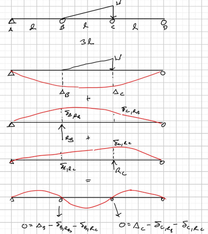
I'd make B and C your redundancies. Solve the statically determinate beam, AD. Use the method of cuts to determine the bending moment curve (on each of the three spans) and integrate. Calculate the deflection at B and C; call these DB and DC

apply a unit load at B, solve the displacements at B and C, call these dBB and dBC.

similarly apply a unit load at C, solve for displacements at B and C, call these dCB and dCC. Note dCC = dBB and dCB = dBC (by symmetry)

Then (phew !) ... DB = PB*dBB + PC*dCB (or DB = PB*dBB + PC*dBC) and DC = PB*dBC + PC*dCC (or DC = PB*dBC + PC*dBB)
I know a lot of letters but dXY is the unit displacement at Y due to a load at X.

I don't think your beam deflection formulates will help much ... as you need deflection at a point, not max deflection.

"Wir hoffen, dass dieses Mal alles gut gehen wird!"
General Paulus, Nov 1942, outside Stalingrad after the launch of Operation Uranus.
 
Screenshot_2024-09-13_155144_obnjqi.jpg
 
LFRIII said:
I am trying to solve the following problem which is in the method of superposition section of my Strength of Materials textbook. I am stuck and am wondering if anyone could point me in the right direction.

A beam of length 3L is supported by four supports, A, B, C, and D from left to right. The distance between any two supports is L. Between the two middle supports, B and C is a uniformly varying load with maximum intensity of w. Find reactions Ra and Rd.

I started by eliminating the two redundant reactions at A and D and used Case 10 Simple Beam with Uniformly Varying Load (see attached) to find the slope at points B and C. Then used Case 9 Simply Supported Beam with Couple Moment at End to find the moments a points B and C. From there I have tried many things without success.

The book gives the answer: Ra = wl/45; Rb = wl/36.

Your approach should work if you do everything correctly. Celt83's approach is also correct.

You are asked to find Ra and Rd. The book answers are for Ra and Rb. They will not be the same.
 
BARetired said:
You are asked to find Ra and Rd. The book answers are for Ra and Rb. They will not be the same.

I suspect that was a typo. I checked the result in my continuous beam spreadsheet and got exactly the same result for the two end reactions.

Also the internal reactions will be in the opposite direction to the end reactions.


Doug Jenkins
Interactive Design Services
 
it doesn't matter which reactions you're asked for, you pretty much have to find all of them. ok, maybe not the final calc of two, but you have to work through the whole solution process.

all I'd add to celt's sketch (better than m word salad) is delta_c, Rc = delta_b, Rb and delta_b, Rc = delta_c, Rb ... by symmetry.

and you might be able to simplify the problem by putting a point load at the centroid of the distributed load ... this is equivalent for external reactions (but not for moments in the middle span).

"Wir hoffen, dass dieses Mal alles gut gehen wird!"
General Paulus, Nov 1942, outside Stalingrad after the launch of Operation Uranus.
 
rb11957 said:
and you might be able to simplify the problem by putting a point load at the centroid of the distributed load ... this is equivalent for external reactions (but not for moments in the middle span).

No, for a point load applied at the centroid of the distributed load the centroid of the reactions will be the same but each of the reactions changes. The slope of the beam at the two internal supports will change, so the end reactions will change, so the internal reactions must also change.

If I have my numbers right, for a point load W at 2/3 along the central span, the end reactions are Left: 22W/405; Right: 32W/405

Doug Jenkins
Interactive Design Services
 
Gentlemen:

Thank you for your responses above. I am still not able to get to the finish line on this problem using your input. I have attached a word document showing what I have done so far. If one of you could take a look and show me the steps to get to the answers, I would appreciate it.

Thanks again.
 
 https://files.engineering.com/getfile.aspx?folder=baa1815e-d1bf-4eff-9db6-9b62ff5add7a&file=Problemset_9-1.docx
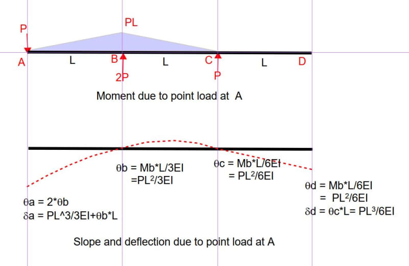
Deflection at A is made up of 3 parts, Delta [W], Delta [Ra] and Delta [Rd]
Delta [W] (upward) = L*Slope B. Delta [Ra] = -2Ra*L^3/3EI. Delta [Rd] = -Rd*L^3/6EI. [square brackets means due to]
I use the negative sign for Delta Ra, Rd because they both cause downward deflection. Alternatively, could use positive sign and they would each turn out to be negative.

So Deflection at A = The sum of those three deflections = Zero.
A similar equation can be made for Deflection at D, which also must equal zero.

Now you have two equations and two unknowns, so solve for Ra and Rd.

Capture_lpnhn6.jpg
 
I should point out that the expressions for Delta Ra and Delta Rd would be different if L was different for each beam.
Because they are all equal, the slope at B and C is zero due to reactions Ra and Rd.

Edit: Ignore the last comment; it is incorrect.

 
When I have a problem such as this (indeterminate, changing section / modulus with length, multiple forms of loading, etc), I usually use symbolic solving software and use 1st principals. Set up the BM equation in terms of the unknowns and then generate the equations to solve for the unknowns, i.e. setting displacements / gradients to zero at supports and summing moments / vertical forces. It usually works for me!
 
I agree that it would be quite interesting to look at things like this using symbolic solving software, but for practical purposes if the end result required is some simple coefficients for a particular span arrangement and loading, it seems to me far simpler (and less error prone) to just do a numerical analysis with unit spans and loads, and take the coefficients directly from that.

Doing that in this case, the results are (with upward reaction positive):
Ra = -0.02222 = -WL/45
Rb = 0.18333 = 11WL/60
Rc = 0.36667 = 11WL/30
Rd = -0.02778 = WL/36

Reaction sum = 0.5 = WL/2

Doug Jenkins
Interactive Design Services
 
It may be less error prone, but does it teach the OP how to do it?
 
I have a much cruder way (than "symbolic software") ... I've the deflected shape a simply supported beam with a point load at "a" set up in excel, so I can quickly set up the specific loading.

"Wir hoffen, dass dieses Mal alles gut gehen wird!"
General Paulus, Nov 1942, outside Stalingrad after the launch of Operation Uranus.
 
The Op is doing this by hand calculations not by spreadsheets.
I think Celt83 would be the way I would do it, the only problem is that the formula sheet does not allow for the triangular loading deflection at B and C.
 
I would solve one problem by hand too. I set up a s/sheet to solve similar problems quickly.

Solving one problem by hand is (to an extent) simpler than using the s/sheet approach.

"Wir hoffen, dass dieses Mal alles gut gehen wird!"
General Paulus, Nov 1942, outside Stalingrad after the launch of Operation Uranus.
 
rb1957 your way is celt83's way except that celt showed it diagramatically.

But as you say the presented formulas would not be very helpful because you need deflection at points B and C not maximum deflection.
 
I'm deliberately taking things on a tangent... Take the bait if anybody feels inclined.

BAretired said:
It may be less error prone, but does it teach the OP how to do it?
But in the modern day of great software is it actually useful the learn these techniques? There are plenty of very good mathematical techniques to solve complex structural problems but unless they improve a deeper understanding then I'm not sure of their broader benefits.

In my opinion a good engineer need:
-Tools to solve a problem.
-Instinct/Understanding to error check and have a gut feel for the problems/issues that need to be addressed.


The former is readily provided by computers these days. The later can be provided by multiple paths including mathematical, visual or other fuzzy gut feel methods. Personally I would never solve such a problem by hand these days. It isn't fast nor is it helpful for my understanding.


While some might say this seems to ignore the fundamental mathematics. Unless somebody is doing everything by hand with no calculator then they are ultimately using some computational tools along the way... (For what it is worth I did a mathematics undergraduate degree where calculators were largely banned from exams.)
 

Part and Inventory Search

Sponsor