Eng-Tips is the largest engineering community on the Internet

Intelligent Work Forums for Engineering Professionals

Statically Indeterminant Beam Problem 7

LFRIII

Mechanical
Sep 2, 2022
16
0
1
US
I am trying to solve the following problem which is in the method of superposition section of my Strength of Materials textbook. I am stuck and am wondering if anyone could point me in the right direction.

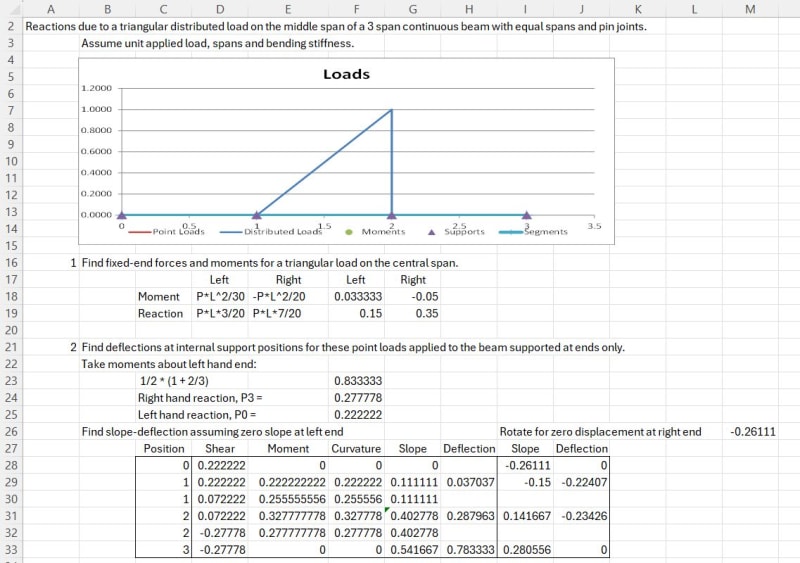
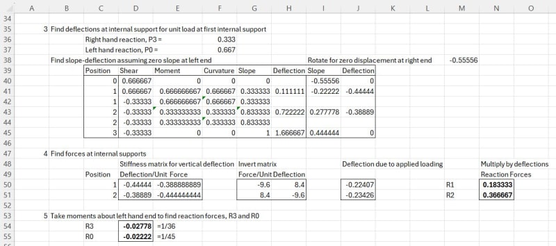
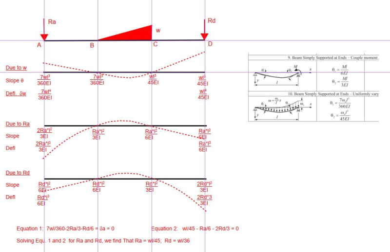
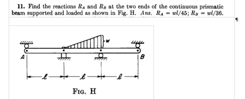
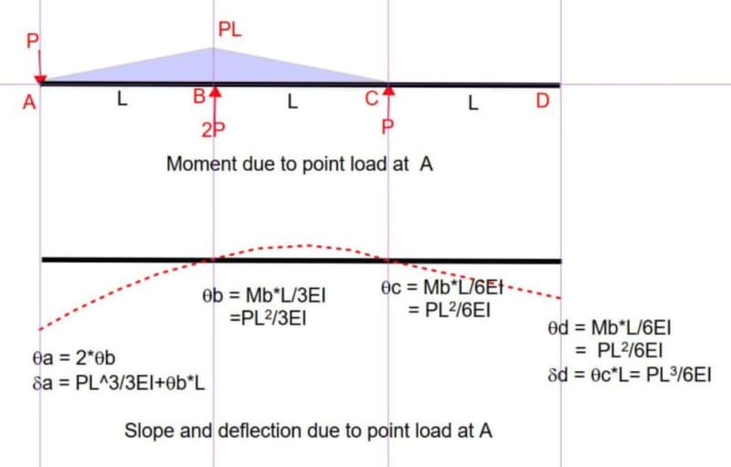
A beam of length 3L is supported by four supports, A, B, C, and D from left to right. The distance between any two supports is L. Between the two middle supports, B and C is a uniformly varying load with maximum intensity of w. Find reactions Ra and Rd.

I started by eliminating the two redundant reactions at A and D and used Case 10 Simple Beam with Uniformly Varying Load (see attached) to find the slope at points B and C. Then used Case 9 Simply Supported Beam with Couple Moment at End to find the moments a points B and C. From there I have tried many things without success.

The book gives the answer: Ra = wl/45; Rb = wl/36.

If anyone can help with this, I would appreciate it.

[URL unfurl="true"]https://res.cloudinary.com/engineering-com/image/upload/v1726255246/tips/Beam_Deflection_Formulae_iqr6vc.pdf[/url]
 
Replies continue below

Recommended for you

oh human909 ... "hook, line, and sinker"

If we don't understand the method, if the method is some black box that we provide inputs to and believe the output, then we're nothing more than a "cargo cult".

Take your position to it's limit ... why learn math when we have calculators ?

I personally detest "online beam calculators". They produce nice looking pictures, blah, blah, blah, and their results are taken as fact (which I accept they probably are) but how hard is it to solve a beam, even a statically indeterminate one like this ? What they do, in the people I've seen using them, is erode that fundamental understanding of structures and our analysis of them. As a manager I had to do as assessment of potential university grads. People, recent grads, applying for a job in stress analysis couldn't "derive the bending moment equation for a simply supported beam with a single point load (using the method of cuts)". People with a Masters couldn't. In 5 years, maybe 5 could; including one guy who had the initiative to ask someone who'd done my test what the question was (he got extra points).

"Wir hoffen, dass dieses Mal alles gut gehen wird!"
General Paulus, Nov 1942, outside Stalingrad after the launch of Operation Uranus.
 
This being a textbook question usually they will build on previous problems so if you just jump in at random you’ll be missing the previous works the authors planned for. In my experience for a problem like this there was probably an earlier problem asking for the deflection at a point of a single span beam with triangular load in the span (likely this was in the double integration chapter).

If your jumping in as someone out of school for a refresh then you should already have the knowledge to generate the functions for the deflections.

The approach of removing the two end supports and looking at it as two cantilevers should give the same answer but maybe a bit more work compared to removing the interior supports with the book keeping of tracking through joint slopes and deflection on opposite ends.

“ Instinct/Understanding to error check …”
Without being able to derive or having derived the formulas I would argue that one would lack both the instinct and understanding necessary to error check the software.

Starting to see this manifest as some textbooks have started removing chapters on slope-deflection, etc. and instead have placed them in an appendix opting to jump straight to 2d stiffness method. I’m not entirely against this as a lot of the software is stiffness based but think there is some loss of instinct by dropping some of the classical methods.

Excerpt from a recent analysis text by Nielson and McCormac:
IMG_0773_hwnfg9.jpg
 
"The approach of removing the two end supports and looking at it as two cantilevers" ... that will give the wrong answer as it assumes zero slope at the interior supports, and I don't think you need to keep track of the end slopes (since nothing is constraining the end slopes (the way that the simple support constrains the end deflection).

you can remove the two end simple supports (instead of the two interior supports, which gives a simple beam problem). and now the determinate solution is a beam with two overhangs. A simplification you gain with this assumption is the the end deflections are due to the slope of the overhand ... deflection_A = slope_B * L; and the unit loads are simplified by symmetry ... deflection A due to load at D = deflection of D due to a load at A, deflection at D due to a load at D = deflection at A due to a load at A.

Maybe another simplification is ... the slope at the supports (B and C) is indpendent of the overhangs. But to determine the slopes at the supports you need to work through the full solution (ie calc displacements) since (I think) the boundary conditions (to solve the integration) at displacement and not restriction on slope; unless you have a worked answer from a text.

"Wir hoffen, dass dieses Mal alles gut gehen wird!"
General Paulus, Nov 1942, outside Stalingrad after the launch of Operation Uranus.
 
rb1957 said:
"The approach of removing the two end supports and looking at it as two cantilevers" ... that will give the wrong answer as it assumes zero slope at the interior supports, and I don't think you need to keep track of the end slopes (since nothing is constraining the end slopes (the way that the simple support constrains the end deflection).

It does not assume zero slope at B and C. Look at my sketch for the effect of point load at A. It is a perfectly valid way to analyze the problem.

 
LFRIII said:
I am trying to solve the following problem which is in the method of superposition section of my Strength of Materials textbook. I am stuck and am wondering if anyone could point me in the right direction.

I remind everyone that the OP was studying a textbook which suggested the method of superposition and asked for help from E-T. I realize there are several other methods which could be used. In my opinion, a structural engineer, even in this day and age, should be familiar with at least a few of the hand methods.
 
rb1957 said:
oh human909 ... "hook, line, and sinker"
[wink]
I am in some ways playing devils advocate here. But I do truly do believe that there should always be a focus on concepts rather than tedious mathematics. Though often those concepts are mathematical they could quite easily be visual too which CELT's explanation is mostly.

rb1957 said:
If we don't understand the method, if the method is some black box that we provide inputs to and believe the output, then we're nothing more than a "cargo cult".
Well as an aside there is no single method as this thread shows. Further more the black box method isn't similar to hand based methods anyway. So how does understanding the hand method help understand the black box software? Surely by understanding concepts under behaviours we can understand both answers without any calculations or with fewer calculations?

Also mathematics can readily be a black box tool as well. In fact many areas of mathematics are badly taught in a black box fashion by teachers who themselves don't have a deep understanding. I'm sure I'm not the only one in this thread who sometimes annoyed their high school teachers because I asked, "but why" too many times.

Back to my point:

I DO believe You can be an excellent engineer without being easily able to hand calculate things.

I don't believe you can be an excellent engineer without always having the question 'WHY' in your head.


The latter question could point you down a mathematical path but not necessarily.

rb1957 said:
Take your position to it's limit ... why learn math when we have calculators ?
I don't think the that is the same. Calculators do some simple and a few less simple mathematical functions. Mathematics is alot more than that. Likewise, I'm not saying don't learn engineering because we have engineering software.

Anyway... I have likely said all that is needed on this tangent. I welcome further disagreement if you or other feel inclined. [yinyang] [yinyang]


Despite my above arguments I have great respect for anybody who can quickly and elegantly provide an clear solution problems. In this thread I feel that was most elegantly done by CELT.
Also as already mentioned I have a very deep background in mathematics. I'm certainly not anti mathematics.
 
The main point of my previous post was that it simplifies the analysis to do the calculations assuming a unit maximum load, unit span, and unit flexural stiffness. You can then do the calculation with a beam analysis spreadsheet, an FEA program, a pen and paper and slide rule, or anything in between.

I have attached screenshots of a "hand-calculation" on a spreadsheet, and also attached the spreadsheet file. The method used is essentially as suggested by Celt83, which is also used in my Conbeam spreadsheet, which is what I used for my previous calculations.

I agree that it is worth learning the basic principles of beam bending, and how these are combined to calculate beam actions and deflections, from simple beams through to complex structures. I also think that setting up these calculations in spreadsheets is both a great way to learn, and useful for real applications.

Here are the calcs:

Engtips16Sep24-1_sv0xgi.jpg


Engtips16Sep24-2_tpiimg.jpg


Doug Jenkins
Interactive Design Services
 
OP has not abandoned ship.

I have been following this discussion closely and have enjoyed both the philosophical and technical responses. The two most recent posts have been most helpful. I had been unable to see the forest on this problem and now have two ways of solving the problem that I want work through myself. I am going to be adding the solution to this problem to a spreadsheet we use for a real-world application and as human999 suggested above I need to work through the two solutions you have given me by hand before I move forward.

The next question I am going to ask is how to solve the same beam configuration if the interior supports are not rigid. In our real-world application these supports have some flexibility. We have not determined the spring constants but may be able to estimate it empirically.

So, if you are game, take a look at how to add not-zero deflections at the two interior supports.

And thank you all for all the help you have given to me so far...
 
WoW .. that explains a lot ... I had misread the initial problem as 4 simple supports (like the question being asked now) ... so go back to my posts ... a "simple" doubly redundant beam.

I'm surprised that the solutions provided work if the inner supports are fixed. I'd thought that meant 4 redundancies ... but I can see that the fixed supports "isolate" spans of the beam to simplify the outer spans as propped cantilevers (2 redundancies); but then we haven't solved the middle span (another 2 redundancies),

"Wir hoffen, dass dieses Mal alles gut gehen wird!"
General Paulus, Nov 1942, outside Stalingrad after the launch of Operation Uranus.
 
rb1957 - I'm pretty sure the original question was for 4 rigid pinned supports and he is now asking for 4 spring pinned supports. There is no suggestion of moment fixity, and if the internal supports had fixed moment restraint the problem would effectively be for 3 independent spans.

Doug Jenkins
Interactive Design Services
 
Doug:

I may have not been clear. The two outside supports are rigid (bearings). The two interior supports are shaft seals that have some flexibility. We originally thought that the shaft seals were rigid enough to be considered fixed supports but we now believe that they may flex enough to make a difference.
 
The analysis to date assumes a pin support at A and roller supports at B, C and D. Supports A and D resist uplift with current loading, but that will change if and when gravity load is added to the exterior spans. If the foundation sinks due to soil settlement, that can be discussed, but usually it is assumed that the foundation permits rotation but prevents settlement.

[highlight orange]Edit: The sketch below is from an earlier post by the OP. It shows the pin support at the second support from the left, which we are calling B. One support is considered a pin (doesn't matter which one), the other three are rollers.[/highlight]

Capture_ggjxd8.jpg
 
BAretired

Neat solution.

But where did you get the deflections (and slopes) for load cases in line 2 and 3 ?

Its not from the formulas pasted to your solution.
 
Civeng80:
Recognize that the loaded overhang can be simplified to a vertical load and moment at the near joint. The vertical load goes directly to the support, the rotation at each end of the span due to the joint moment is per BA’s formulas.

Deflection of the point loaded overhang is the fixed-free deflection + (joint rotation x L)

Deflection of the unloaded overhang is just joint rotation x L.
 
civeng80 said:
But where did you get the deflections (and slopes) for load cases in line 2 and 3?
Its not from the formulas pasted to your solution.
It is as Celt83 stated, but I also showed it in a previous post, copied below.

Capture_wb8n0j.jpg
 
different loading, no?

"Wir hoffen, dass dieses Mal alles gut gehen wird!"
General Paulus, Nov 1942, outside Stalingrad after the launch of Operation Uranus.
 
Back
Top