I have forgotten my statics class.
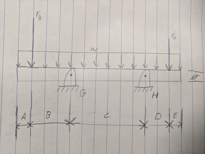
Ultimately I am trying to determine Critical Speed of a shaft supported by two bearings with loads on each end. I am struggling with correctly calculating the total deflection in the beam. We have several calculators and they all give different results so I am tasked with building a new one that yields correct results that we can agree on and stand by. The situation as shown in the picture has a round shaft of length (A+B+C+D+E=L) supported by two bearings. Bearing G is fixed, and bearing H is an expansion (can move left and right slightly). The shaft has a uniform load w (its weight). It also has two forces acting on it, Fb and Fa. if it helps it is a steel shaft, but we use a variety of steels and various temperatures so the modulus may change.
if someone can solve this for total deflection and show their work so I can follow along and apply it to our applications I would greatly appreciate it. I have been mulling over this for days and cant seem to remember how to correctly do this.