Eng-Tips is the largest engineering community on the Internet

Intelligent Work Forums for Engineering Professionals

Steady-State (Static) vs Dynamic Acceleration. What's the Difference?

Status
Not open for further replies.

Dikuza

Aerospace
Jan 18, 2017
35
0
0
AU
Regarding the design of spacecraft structures, what is meant by "static" and "dynamic" acceleration?
Any help is much appreciated!

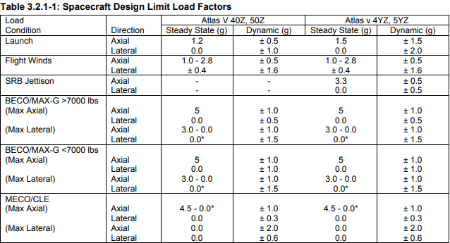
Launch vehicle providers always include a table of Spacecraft Design Limit Load Factors in their user guides to use for spacecraft preliminary design.
For example, the below table is taken from the ULA Atlas V User Guide:

Screenshot_2024-01-15_152320_dpjppw.png


Another example is from Wijker's book Spacecraft Structures:

Screenshot_2024-01-15_152034_flx6ea.png


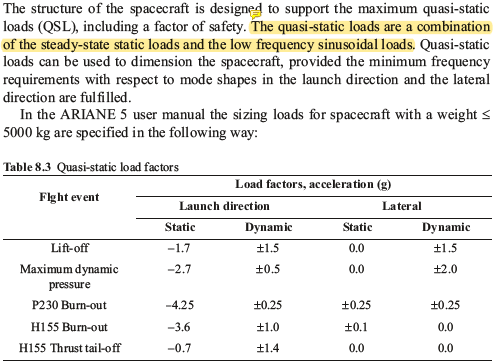
I've highlighted what seems to be the author's description of the two components.
From another document (ECSS-E-HB-32-26A: Spacecraft Loads Analysis Handbook), they define "steady-state acceleration" as the same as static acceleration (constant magnitude and direction) and can be thought of as the average acceleration through the center of gravity.
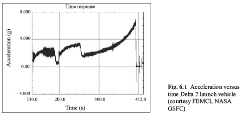
I interpret this as if you were to remove all the vibration from the following figure, resulting in a smooth line. Is this correct? If so, it seems weird to consider steady-state acceleration the same as static. Static to me means constant with time, which obviously it is not. I guess this is why the term "quasi-static" is sometimes used instead? Static acceleration is a very confusing term to me.

Is dynamic acceleration then the acceleration due to the low-frequency sinusoidal loads such as POGO or random vibration due to acoustic noise from engines firing? This would be the noise in the below image.

Screenshot_2024-01-15_153540_bbntft.png


Second part of the question is how are the loads actually used? I understand they are applied to the fixed spacecraft's CG, but do I add them together?
For example, using Table 3.2.1-1 from Atlas V, to cover the worst-case, I would run these two cases?
[ol 1]
[li]Max axial[/li]
This occurs during BECO and I would apply 6 g's axially (steady-state + dynamic) and 1.5 g laterally together at the same time

[li]Max lateral[/li]
This occurs during launch and I would apply 3.0 g's axially and 2 g's laterally together at the same time
[/ol]
 
Replies continue below

Recommended for you

While I have no background in spacecraft, I do recall 44 years ago some basic from my "Statics and Dynamics" course. What is referred to as "dynamic acceleration" is probably just the next derivative of acceleration, or Jerk
Position
Velocity
Acceleration
Jerk
and a quick internet check shows there are more.
Fourth, fifth, and sixth derivatives of position

I frequently think of this when politicians talk about:
Budget (Position)
Debt (Velocity)
Increases in Debt (Acceleration)
Deficit spending (Jerk)
Increases in deficit spending (Snap)
 
@comcokid, I appreciate the response but yeah it's definitely not jerk. As Greg pointed out, this would make the units g/s and also is never really accounted for in actual analysis as far as I'm aware
 
So, "static acceleration" is confusing because it is a bit of an oxymoron. The term "quasi-static" in some of the materials you posted is much better.

Typically, from a structural engineering standpoint, our systems are in a state of acceleration, and not really in static equilibrium. But as you may recall from college, treating a system from a dynamics standpoint can be significantly more challenging than using the equations of static equilibrium.

However, D'Alembert's principle is often used to treat accelerating systems quasi-statically using a fictitious "inertial force".

We have to be careful because this is not always what is meant by "dynamic loading". Often times that is referring to vibration induced loads, impact loads (which generally cannot be treated using simple dynamics if the structure is not going to behave as a rigid body), or myriad other things.

A good example might be for a rocket. Generally from a structural analysis standpoint, the mission profile would be split into flight segments, and various load cases would be developed to represent the extremes in each segment.

We might have an ascent-representative load case. In such a case, there could be a constant vertical acceleration of, say, 6G. We could at least treat this quasi-statically. But what about the vibration loads? Well, there are other techniques such as Miles' equation, etc. that can be used to get a quasi-static load accounting for the vibration profile.

That is what I suspect you have here. The "static" values are the inertial load factors under D'Alembert's principle that are required for the constant acceleration. The +/- "dynamic" values are on top of those and come from the superposition of the vibration profile.

Keep em' Flying
//Fight Corrosion!
 
Maybe if you had read the ULA book you'd have come across this

3.2.1 Spacecraft Design Load Factors
Design Load Factors (DLF) in Figure 3.2.1-1 and Table 3.2.1-1 are for use in preliminary design of primary
structure and/or evaluation of compatibility of existing SC with Atlas V LVs. Factors are provided for each
transient event that produces significant SC loading. The total DLF for any direction can be determined by
addition of the quasi-steady state and oscillatory dynamic components provided
. Uncertainty factors related
to SC design maturity are not included in the DLF definitions.
The load factors were derived for application to the Center of Gravity (cg) of a rigid SC to generate a
conservative estimate of interface loading. The load factors are applicable only to standard payload adapters
as defined in Section 5. The actual responses of a SC due to LV transients will depend on its specific static
and structural dynamic characteristics; however, the values provided have generally proven conservative for
SC in the weight range of 1,230 to 9,100 kg (2,720 to 20,062 lb). The SC cantilevered fundamental mode
frequencies are assumed to be a minimum of 8 Hz lateral and 15 Hz axial to ensure applicability of the
design load factors. SC that do not meet these criteria or those with non-standard payload adapters will
require configuration specific analyses for assessing compatibility with Atlas V LVs.
Coupled Loads Analyses (CLA) are dynamic analyses conducted as part of the mission integration activity to
provide SC primary and secondary structure loads, accelerations, and deflections for use in design, test
planning, and verification of minimum margins of safety. CLA results supersede loads derived from the Table
3.2.1-1 load factors.

Cheers

Greg Locock


New here? Try reading these, they might help FAQ731-376
 
my interpretation of the first table is "static" = mean and "dynamic" = "amplitude".

in the normal case, with low frequency dynamic loads, mean+amplitude would be a conservative quasi-static load.

the issue with dynamic loads is when the load frequency is close to the natural frequency of the structure, and so you get dynamic magnification (dynamic factors > 1 for quasi-static loads).

"Hoffen wir mal, dass alles gut geht !"
General Paulus, Nov 1942, outside Stalingrad after the launch of Operation Uranus.
 
It looks like an envelope to me.
The "steady-state" acceleration is the middle of the envelope, and the dynamic is the distance to the edges.
For instance, the axial acceleration at launch in the first column has a range between (1.2+0.5)=1.7g to (1.2-0.5)=0.7g.
This isn't surprising as "pogo" is a substantial factor in rocket design.
But what's missing is frequency - If it's an oscillation, then the frequency determines how much energy is being transferred into your item of mass...

I don't normally write these factors that way, especially since the "middle of the envelope" isn't likely to be useful information.

That said, I cannot explain the ranges of values under steady-state.
 
Status
Not open for further replies.
Back
Top