Continue to Site

Eng-Tips is the largest engineering community on the Internet

Intelligent Work Forums for Engineering Professionals

  • Congratulations waross on being selected by the Eng-Tips community for having the most helpful posts in the forums last week. Way to Go!

Steam Control Valve Specification Problem ( Contd)

Status
Not open for further replies.

Pavan Kumar

Chemical
Aug 27, 2019
334
Hi All,

In continuation to this thread I wanted to discuss the following finding. I calculated the pressure drop for superheated steam using Adiabatic, Isothermal, Using Polytropic approximation of Compressible flow with friction, Darcy's equation using Net expansion factor ( using the paper by William Kirkland attached in the previous thread), and finally using AFT Arrow Software. The comparison of the results is copied below.
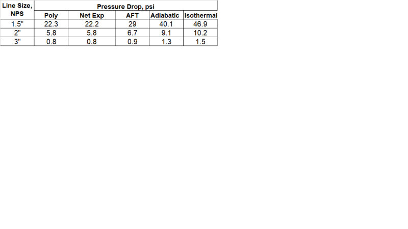

DP_Comparizon_ewtpde.png


I have attached the spreadsheet I developed by following the paper by William Kirkland with this message for your reference.

My question is that there is vast difference in pressure drop calculated by Adiabatic, Isothermal and the Polytropic approximation. Also the values calculated using the Polytropic approximation and using the Net Expansion factor are close to the values calculates using AFT Arrow software. I am leaning towards using the polytropic approximation and wanted your suggestions and guidance on it. Also since this is steam I still have to calculate the heat loss through the pipe and insulation to calculate the steam condition namely temperature and quality at the pressure calculated using the pressure drop calculation. Is that correct?.

Thanks and Regards,
Pavan Kumar

 
Replies continue below

Recommended for you

Hi,
I'm not sure I understand what you are trying to do . Your system should include the steam valve . A sketch will help .
For calculation you should iterate on f value , initialize your calculation with f from Von Karman. It's my way to perform the calculation .
(attached an excel sheet) .
Regarding the different models , Isotherm should refer to long pipe not insulated , Adiabatic short pipe insulated .
Note : Check whether the heat losses are significant and revise your assumptions accordingly. If yes more iterations are needed (temperature , Physical properties) .
Good luck
Pierre
 
 https://files.engineering.com/getfile.aspx?folder=63a62ecc-ea27-4e1c-85a8-003ef996cad3&file=A_polytropic_approximation_compressible_flow_with_fittings.xlsx
pierreick,

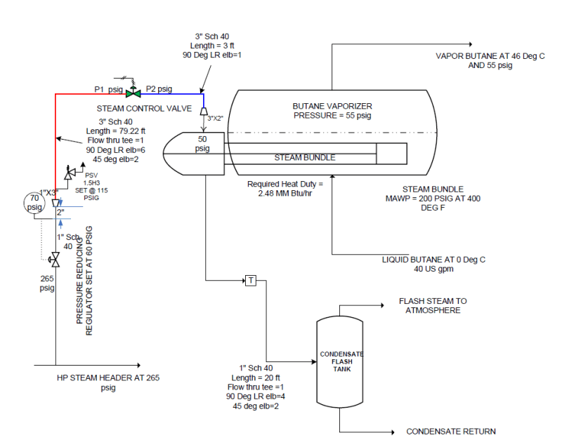
Please refer to the previous thread, link copied below. The sketch is also provided in the previous thread.


My goal is to specify the upstream and downstream pressure of the Steam Control Valve in question for three different flowrates. The inlet line is 3" Sch 40 CS pipe, 79.7 ft long with some fittings. The line is insulated with 2" mineral wool. The outlet line is just 3 feet long, also 3" Sch 40 CS. As you can see the calculation of the upstream and downstream pressure depends on pressure drop. HP steam at 265 psig is step down to 70 psig across a let down regulator which then flows to the steam control valve through the 79.7 feet long 3" pipe . The question I am asking is using adiabatic model is giving a pressure drop higher than that calculated using the Polytropic approximation. The line is long and insulated so adiabatic model cannot be used as per your guidance. So the polytropic approximation is adequate then?. Besides the result from the polytropic approximation calculation is the close the value calculated using AFT Arrow software. The other question I asked is to calculate the temperature of the steam at control valve inlet I have to take in account of the heat loss through the pipe with insulation?. I have detailed the methodology in the previous thread.

I see you also used the Polytropic approximation in your spreadsheet albeit there are some differences.

Thanks and Regards,
Pavan Kumar
 
In you scenario, having access to AFT Arrow I'd just use its value. Overall, the software is good and the results should be close to it.

It is expected that both the adiabatic and isothermal calculations would result in a larger pressure drop.

Isothermal: The initial temperature is maintained during the entire length, final velocity should be the highest one.

Adiabatic: Temperature will vary through an isenthalpic expansion throughout the flow length. Decreasing the temperature will result in a higher density than the one found in the isothermal, so velocity will be lower than that one.

In real life: the stream loses pressure by friction and loses temperature by heat exchanged (cools down), so density will be the highest and velocity the lowest. I imagine that your AFT Arrow model is modeling the heat lost through the insulation and therefore correctly computing the overall change in density/velocity.

Daniel
Rio de Janeiro - Brazil
 
Hi danschwind,

AFT Arrow takes heat loss input from the user, it doesnot calculate automatically. I provided the heat loss from the 3" pipe with insulation ( 77472.6 7472.6 Btu/hr) and allowed AFT Arrow to calculate the pressure drop and outlet temperature. Comparing the results using no heat loss model ( adiabatic ) in AFT Arrow I got the pressure drop in both cases same with only increased temperature drop in the case of the heat loss model. I want to use my spreadsheet as I know the basis for it and plus the actual process is between the isothermal and adiabatic process making use of polytropic index more appropriate. While I am able to calculate the pressure drop as illustrated in my spreadsheet, I am calculating the temperature drop by taking into account of the steam specific enthalpy at pipe inlet substracting the heat loss and checking the steam condition at the calculated specific enthalpy and pressure, though in actuality these two go together. Can I use this methodology?.


AFT Arrow Results

Csse1 : Adiabatic

Mass flow = 2659.38 lb/hr
DP = 0.90 psi
T1 = 348 Deg F
T2 = 348 Deg F

Csse2 : With Heat Loss Model

Mass flow = 2659.38 lb/hr
Heat Loss = 77472.6 Btu/hr
DP = 0.90 psi
T1 = 348 Deg F
T2 = 343 Deg F

Thanks and Regards,
Pavan Kumar
 
Pavan,

I'm pretty sure that Arrow can compute the heat transfer by itself. Pipe Properties > Heat Transfer > Convective Heat Transfer.

Also, I disagree with you that your process is between adiabatic and isothermal. Your process is in essence a cooled process - you are actively losing heat through your insulation while simultaneously expanding. The presence of the insulation of course makes this effect very diminished, so it will be close to adiabatic, but in this scenario the adiabatic calculation is more conservative than what is actually happening in real life.

I think it is very good that you are trying to do it "by hand" though. I'm way lazier than that - I think I have a good understanding overall of the phenomena already and I just tend to save time by employing software to do the heavy work for me while I just review the results to see if they make sense or not.

Daniel
Rio de Janeiro - Brazil
 
By the way, I don't "think" in imperial, but I reckon this heat loss value you computed is a little excessive.

Daniel
Rio de Janeiro - Brazil
 
Hi danschwind ,

There was typo in my heat loss value. The value was supposed to be 7472.6 Btu/hr. I have edited and corrected above message now. Yes you are right Arrow can calculate via convective heat transfer however I am not sure if that is correct way as the resistance to heat is due to insulation ( conduction ) and ambient air surrounding the pipe over the insulation (convection + some radiation). I calculated my heat loss accounting for both these effects using the methodology given in DQ Kern's chapter "Conduction".

The calculated pressure drop using Polytropic approximation is close to what Arrow is calculating. So should I use this value? The pressure drop calculated by adiabatic process is almost twice of the value calculated Polytropic approximation. I will complete all the calcs tomorrow and post the results for you all to see.

I too used to use AFT Arrow and AFT Fathom extensively, but I now prefer doing hand calcs as I want to know the background behind the calcs.

Thanks and Regards,
Pavan Kumar


Heat loss through a pipe is an effect of convection inside the pipe, conduction through insulation and convection through air. I've in the past compared Arrow's results to other software and found that in overall it is a good calculation.

I have never used a polytropic approximation for pressure drop, therefore I cannot say if you should use it or not...

Daniel
Rio de Janeiro - Brazil
 
Hi danschwind,

As you can see in the attached sketch there is a PSV on the line downstream of the regulator that is set at 115 psig. The steam bundle's MAWP is 200 psig at 400 Deg F. I want t calculate the pipe schedule for the 3" pipe using the pipe pressure design formula given ASME B31.1. The maximum pressure the line for the regulator failure case would be PSV Set pressure + 10% overpressure which is 1.1*115 = 126.5 psig=141.2 psia. I want to make sure this is correct.

Thanks and Regards,
Pavan Kumar
 
 https://files.engineering.com/getfile.aspx?folder=3f3153da-1b84-442b-9fb1-7c8eb8f66d0a&file=Butane_Vaporizer_System_Sketch.pdf
Is your system really designed per B31.1 instead of B31.3?

Don't your company have an existing pipe spec where you can see the thickness for the 3" pipe in this service? I'd suggest sticking to that.

Daniel
Process Engineer
Rio de Janeiro - Brazil
 
Hi danschwind,

The line is in LP Steam service so it will be ASME B31.1. There is no pipe spec for the existing line. The existing line size is 1.5 Sch 40 which as per my calculation is undersized. I am replacing it with 3". There are no records on how the sch was decided, so I am calculating it from scratch.

The relieving pressure of the PSV is the maximum pressure the line will see and that will form the basis for the line pressure design. I am sure Sch 40 will serve this purpose but will check with my calculation.

Thanks and Regards,
Pavan Kumar
 
Pavan,

B31.1 is for power piping, so usually applicable to thermo power plants.

Nothing in your process suggests that this is not a process piping - therefore B31.3.

If there is no pipe spec in your company, then suggest you employ a piping engineer to develop one for your. Or, use an applicable, public-available piping spec. Norsok has some, Petrobras as well.
I think PIP will probably have some piping specs as well, but you need to be a member AFAIK.

For LP Steam 3" Sch 40 is enough per Petrobras N-76 spec Bf. For 1.1/2" Sch 80 is suggested.

Daniel
Process Engineer
Rio de Janeiro - Brazil
 
Hi danschwind ,

In our plant we treat the steam piping as per ASME B31.1. Can you share sample pipe specs so that we can develop some here.

Thanks and Regards,
Pavan Kumar
 
Hi danschwind,

I have question on the pressure drop calculation done by AFT Arrow for pipes and fittings. I have a 4" long 1" Sch 40 pipe ,followed by 1" equal Flow thru Tee and then a 1"X3" concentric expander. I calculated the pressure drop through by spreadsheet with those calculated with AFT Arrow.

Flow rate = 2661.1 lb/hr pressure = 70 psig, Temperature = 175.79 Deg C

Using my spreadsheet:
1" Sch 40 pipe - 4" long : DP = 0.62 psi
1" Equal Tee : DP = 3.309 psi
1"X3" Conc Expander : DP = 6.219 psi ( K= 0.837)
--------------------------------------
Total DP = 0.62+3.309+6.219 = 10.62 psi
---------------------------------------
the calculated pressure drop through the Tee and the 1"X3" expander seem to be high and I compared it with AFT Arrow. The results are copied below.


Using AFT Arrow:
1" Sch 40 pipe - 4" long : DP = 0.97 psi
1" Equal Tee : DP = 0 psi ( does not calculate even though I used the detailed model and arranged the side branch ccrrectly )
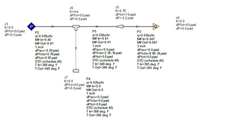
1"X3" Conc Expander : DP = 7 psi (K=0.78, DP friction = 7 psi, wile DP Static Total = -2.2 psi. I want to know why DP Static is - 2.2 psi when DP friction = +7 psi?)

The pressure drop through the 4" long 1" Sch 40 pipe and 1"X3" conc expander are close. There is a question on the difference between Static pressure loss and frictional pressure loss for an expander which is not clear to me and would want your inputs. Also want to know why AFT Arrow is not calculating the pressure drop in Flow Thru Tee. I have attached AFT Arrow file for your reference.

AFT_Arrow_File_kv4ujp.png

Thanks and Regards,
Pavan Kumar
 
I can't say why the software is not calculating the pressure drop through the tee. But, a straight flow through a tee is pretty much a straight pipe.

I'll refrain from trying to explain what the software is doing because I don't work for AFT. Maybe they can assist you through their support.

Regarding your non-software related question, frictional pressure drop in this case is related to how much stagnation pressure (static pressure + dynamic pressure) you lost. When the fluid goes through an expander, it will lose stagnation pressure due to friction but will gain static pressure because your velocity will be lower (hence less dynamic pressure). So, even though your net stagnation pressure is lower, your static pressure might be higher.

Static pressure you measure with a pressure gauge, stagnation pressure with a pitot tube.

Daniel
Process Engineer
Rio de Janeiro - Brazil
 
Hi danschwind,

If I am not wrong Static pressure is the flowing pressure?. When the fluid flows across an expander it loses energy due to friction and also becomes slower. If an energy balance is done the energy lost in friction(permanent loss) and slowing down(recoverable loss) should be taken from the static pressure. In that case the static pressure should reduce and not increase. So the static pressure difference should be positive and not negative correct?.

From what you say the stagnation pressure difference is the true pressure loss due to friction that I should consider?. From AFT Arrow file when I checked to see the stagnation pressure difference it is same as the DP,Friction = 7 psi.

Thanks and Regards,
Pavan Kumar
 
Just think of the equation:

Stagnation pressure = Static Pressure + Dynamic Pressure

When you lose pressure/energy due to friction, you are decreasing the overall stagnation pressure. Stagnation Pressure After = Stagnation Pressure Before - Friction Loss.

If you slow down the fluid in a reversible manner (no friction loss), you are decreasing velocity and therefore increasing static pressure to keep the stagnation pressure the same.

So, as I said, in a expander you are basically losing some Stagnation Pressure but also trading some Dynamic Pressure for some Static Pressure.

Even though in a compressible flow this gets a little bit more complex (in your scenario it is pratically incompressible, so anyway), if you think of the Bernoulli Equation it gets pretty easy to understand what is going on.

Daniel
Process Engineer
Rio de Janeiro - Brazil
 
Sketch_gg28as.png
Hi danschwind,

I need to calculate the static pressure at the exit of the 1"X3" conc expander as seen on the sketch attached. I am calculating the pressure between the sensing line of the regulator where the static pressure is 70 psig and at the exit of the 1"X3" expander. The pressure drop is due to the 1" Flow thru Tee and the 1"X3" expander which I calculated as 3.31 psi and 6.22 psi respectively. So the pressure downstream of the reducer will be 70-3.31-6.22 = 60.47 psi. I then have to add the increase in static pressure due to lowering of the velocity to get the correct static pressure at the exit of 1"X3" reducer.
What I want to know is how do I calculate this increase in static pressure due reduction in velocity.


Thanks and Regards,
Pavan Kumar
 
Status
Not open for further replies.

Part and Inventory Search

Sponsor