Continue to Site

Eng-Tips is the largest engineering community on the Internet

Intelligent Work Forums for Engineering Professionals

  • Congratulations KootK on being selected by the Eng-Tips community for having the most helpful posts in the forums last week. Way to Go!

Steel Bent/Cranked Beam 8

Status
Not open for further replies.

SarBear

Structural
Mar 14, 2022
38
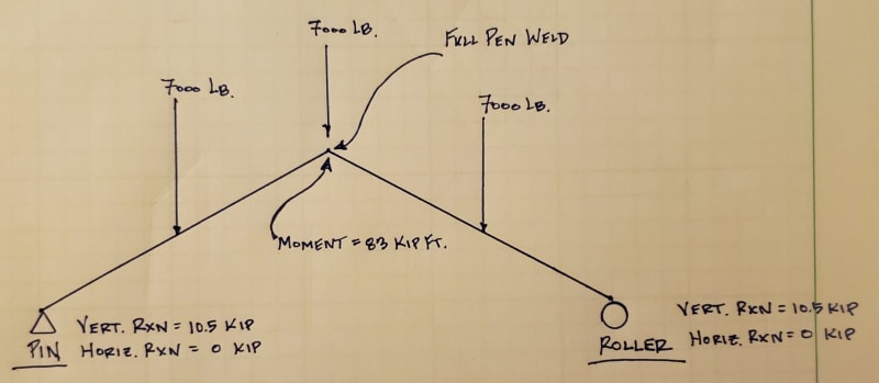
Hi all. I'm looking at a steel pavilion for a friend and am looking for some confirmation/guidance. I mostly work with wood-framed structures so this easy project is challenging me more than it probably should. As you can see below it is a pavilion with 3 steel a-frames/bents/cranked beams, whatever you want to call them. I have modeled the center one in Risa. It will be built with HSS tubes that weld together at the peak. My sketch below shows the pin and roller supports, the point loads from the purlins that hang into the a-frames, and the reactions at the supports. Here are some questions I have:

- Does my diagram make sense with the pin and roller supports?
- Does the 83 kip-ft moment at the ridge sound reasonable? I don't ever use Risa so I'm not sure I've modeled this correctly.
- How can I show that the full-pen weld at the peak can handle the 83 kip-ft moment?
- Any additional feedback would be appreciated
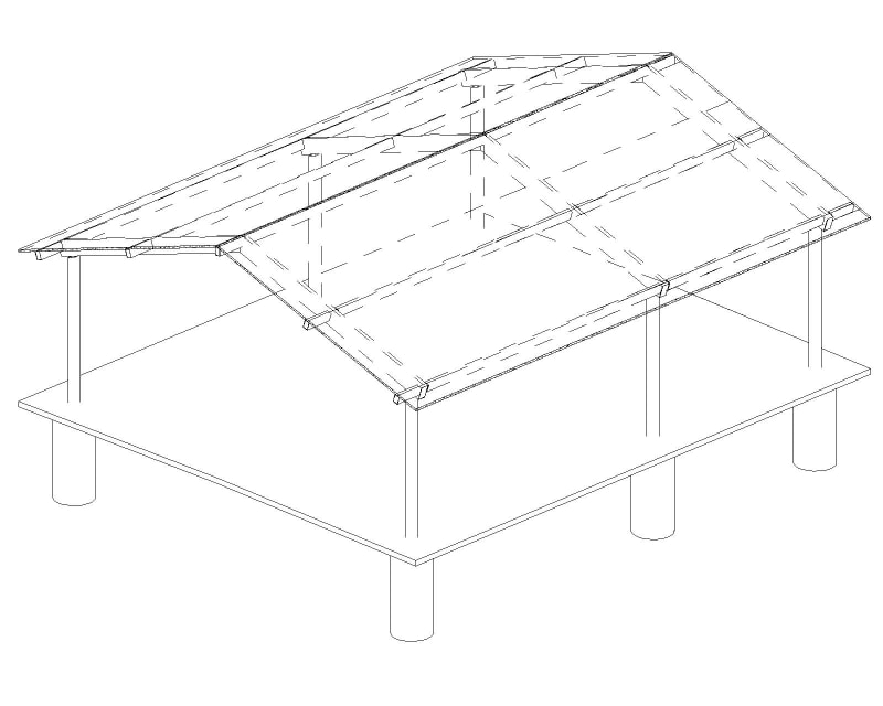
Pavilion_m3al2e.jpg
20240502_232815_azqady.jpg
 
Replies continue below

Recommended for you

Yes the pin and roller makes sense.

The apex is a definite weak point. Simply writing "full pen weld" isn't really enough in my view for such a critical weld.

Also, a mitre cut butt-welded HSS is prone to buckling, because the flange bending forces have nowhere to go except the side walls. You need stiffeners, or end plates, or something, to ensure the webs don't cripple.

Personally, I'd be welding a triangular stiffener into the underside of the apex joint, cut from the same section. Same concept as a haunch.
 
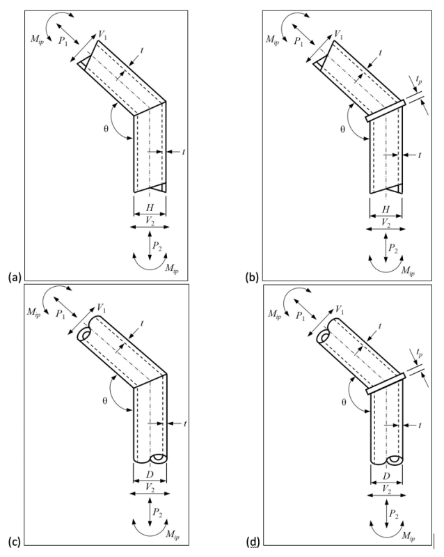
For the mitred connection I'd use a flat plate twice the wall thickness and fillet welds with throat thickness >20% the wall thickness.

This would be easier and faster than a mitred connection.

Tomfh' suggestion of a collar tie likely would improve capacity but you have now given yourself connections that are more challenging to analyse.

Figure-1_cgmohm.png

Suggested connection shown on right.
 
Why not go with a PEMB? Seems like it would be a lot cheaper.
 
Human909 said:
This would be easier and faster than a mitred connection.
It is also necessary with high moments as kinked beams cause weak axis bending of the top and bottom flanges of the tube at the joint.
Pretty tough to analyze
 
- Does my diagram make sense with the pin and roller supports? Yes

- Does the 83 kip-ft moment at the ridge sound reasonable? I don't ever use Risa so I'm not sure I've modeled this correctly. Well, I don't think you provided dimensions, so it's impossible to know. If your point loads are evenly spaced at quarter points, and your overall span is like 24 ft, based on my quick calcs, I think you're probably right. You shouldn't really need RISA for this, but I suppose having a double check is good. The bent beam will experience combined bending and compression.

Some quick advise: Learn how to calculate the moment without using software. Software will burn you very quickly if you don't have any way to check the output. I drew a quick free body diagram to determine the max moment at the peak. I also checked my calculation against the "Concentrated Load Equivalents", Table 3-22a in the AISC Manual. Also, don't trust internet strangers to correctly check your work.

- How can I show that the full-pen weld at the peak can handle the 83 kip-ft moment? The answers above are good.

- Any additional feedback would be appreciated My preference here would be to use I sections and not HSS. An I section should generally be stronger (more economical) for resisting bending and deflection. Of course, there's nothing wrong with using HSS. I know it can sometimes be preferable aesthetically, assuming this will be exposed in the end.
 
OP said:
How can I show that the full-pen weld at the peak can handle the 83 kip-ft moment?

A conservative shortcut is to try to get the job done using only the welds on the HSS side walls. This will underestimate capacity but is simple to do. Once you try to exploit the HSS flanges, things get more complicated with respect to the amount of flange that might be able to be mobilized without stiffeners etc.
 
You don't need a computer to calculate this. The ridge moment is the same for a bent beam as it is for a straight beam. If L is the overall span, M[sub]ridge[/sub] = 10.5*L/2 - 7*L/4 = 3.5L, so if you are correct that M[sub]ridge[/sub] = 83'k, L would be 79.5'.

Offhand, that sounds a tad high, but I don't know how large your friend's pavilion is.

In any case, your friend would do well to retain an engineer to perform a structural design of the building. Ridge moment could be reduced by considering frame action of columns and beam.
 
BAretired said:
If L is the overall span, Mridge = 10.5*L/2 - 7*L/4 = 3.5L, so if you are correct that Mridge = 83'k, L would be 79.5'.
I don't think this is correct. The equation is, but not the answer.
 
Yes, you are correct. 83/3.5 = 23.7'. Duh!!!

Thanks Eng16080. I must have hit the subtract button instead of the divide...and didn't do a sanity check.
 
Thank you all, I appreciate the feedback. Sorry I didn't respond to your messages over the weekend. I got in a minor-ish car accident a couple of days ago and have been dealing with that. Of course it was the other driver's fault and they don't have insurance...

Yes, as you have figured out my overall span is 23.5'.

From most of your comments I get the vibe that there isn't really an actual calculation for the moment capacity of my connection at the peak. I've spent hours looking in the steel manual, searching on Google, and looking through old school books and I can't find anything that's putting me on the right track. Then again, I am the dumbest engineer I've ever met.
 
SarBear said:
I get the vibe that there isn't really an actual calculation for the moment capacity of my connection at the peak
I haven't read every response and I don't often design connections like this, but I doubt anybody is saying that. You should be able to calculate the capacity of any connection per AISC. If, for example, you were to add an end plate sandwiched between the two pieces at the ridge with fillet welds to each piece, you can definitely determine the capacity of those welds and use that to then determine the moment capacity of the overall connection. You can also determine the capacity (or minimum thickness) of that end plate. I'm guessing that most people might use basic rules of thumb in connections like this. Like if the weld is of a sufficient size to be of greater strength than the axial capacity of the HSS wall, then there's no need to provide a more in-depth analysis.

SarBear said:
I am the dumbest engineer I've ever met.
No offense, but you're probably less dumb than you think. Dumb people don't ask questions.
 
SarBear said:
From most of your comments I get the vibe that there isn't really an actual calculation for the moment capacity of my connection at the peak.

I think that's an accurate statement as far as unstiffened moment connections go. It's a pretty common thing for designers to want to do this on smaller applications but, to my knowledge, there is no industry sanctioned design method for dealing with it. A great many dog legged stair stringers are examples of this in my experience.
 
I think stair stringer can be checked, you are just checking something similar to panel zone shear in the web. The HSS is harder because of the weak axis moment in the "flanges".

My main concern with the system as you've detailed it is that it will be quite flexible. Given that you have cantilever columns, you also likely can't call it pin-roller supports, unless you use a roller, in which case I think the roof might roll off the support under snow load.
 
I disagrees on the channel stringers. Channel flanges also have the weak axis moment problem that you described. An HSS bears considerable similarity to a pair of toes in channels after all...
 
Ok, I suppose that is true, the centroid of the flange is eccentric to the web, so there is some flexure that needs to occur somewhere. Given the smaller eccentricity and the fact that stair stringers rarely work that hard it might be more rational to ignore it than in this case though.
 
canwesteng said:
My main concern with the system as you've detailed it is that it will be quite flexible. Given that you have cantilever columns, you also likely can't call it pin-roller supports, unless you use a roller, in which case I think the roof might roll off the support under snow load.
Yes, my model is showing a 3.5" downward deflection at the peak, and then a 2.5" horizontal deflection at the roller support on the right end. Do I need to change my design to a pin-pin? Doing so creates a horizontal force of 19 kips at each end!
 
You should design the columns accounting for the thrust.
The stiffness of your beam/columns will determine your thrust.

Was the 19 kip thrust accounting for the column flexibility?

As a conservative simplification I would design the cranked beam as pin-roller though.
 
CDLD said:
As a conservative simplification I would design the cranked beam as pin-roller though
That's what I've originally done it as, but it creates a 3.5" downward deflection at the peak, and a 2.5" horizontal deflection at the right end. I've got the angled beam bolted to the top of each column so a 2.5" deflection will rotate the column which is unacceptable I'd think.

CDLD said:
Was the 19 kip thrust accounting for the column flexibility?
I mean I only have modeled the A-frame with a pin on one end and a roller on the other end. When I change it to pin-pin that's where the 19 kip thrust comes from.

I just would like the A-frame to be a self-contained thing that only puts vertical load down onto the columns. But with a pin-roller it appears that it's going to rotate the column. With a pin-pin it will push out on the columns with an enormous force.
 
Status
Not open for further replies.

Part and Inventory Search

Sponsor