Eng-Tips is the largest engineering community on the Internet

Intelligent Work Forums for Engineering Professionals

Steel column hairpin rebar 2

Status
Not open for further replies.

enriko12

Industrial
Sep 5, 2020
54
0
0
US
Hi,

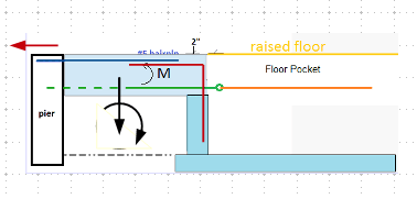
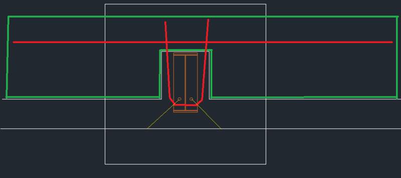
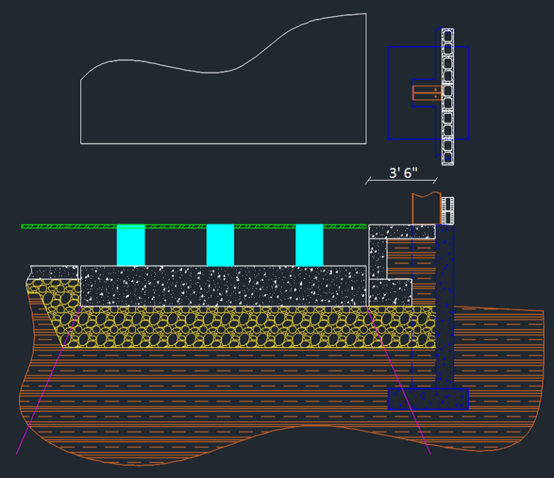
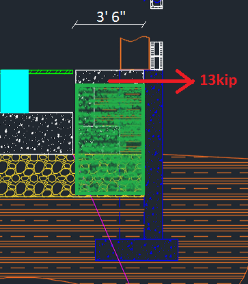
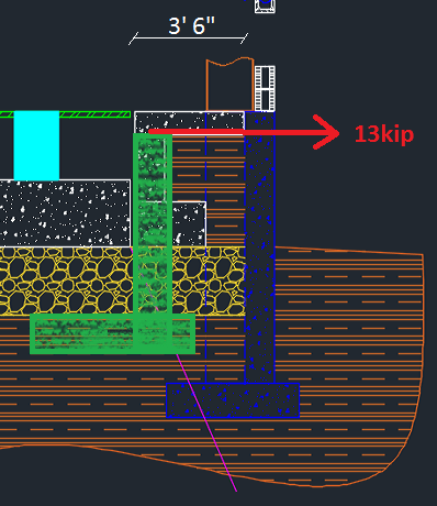
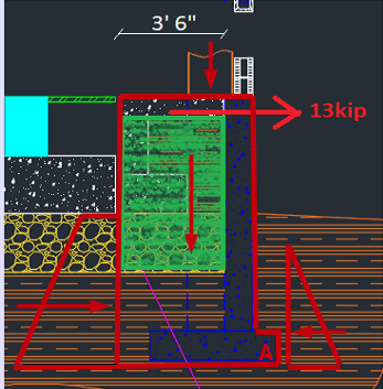
We are working on the old steel building with no original prints available. After contractor removed the old slab, there were hairpin rebars wrapped around column pedestals. I understand their purpose is to provide "some" lateral resistance. Anyone had previous experience with those being damaged/removed and any adverse affects on the structure? How useful are those anyway? It's not like they are going to tie 2 sides of the moment frame together. Control joint are typically cut into interior slabs, so hairpins will rarely tie into more than 1 tile, and sometimes joint are cut right through that rebar. Also, slabs are typically poured last, so those are definitely not helping with any dead weight. I am thinking that single slab tile would add a negligible lateral resistance in comparison to that of the buried spread footing/column pedestal/wall footing.

Any input is highly appreciated!


Replies continue below

Recommended for you

Depending on the demand (calculated as suggested), You can add wall thickness, enlarge footing, or even consider conterfort behind the columns that have lost the connection with interior slab.

 
I did measure the actual frame members and ran it through FEM. Using the same loads as jimstructures, I got 13.2 & 12.5 kips of horizontal reaction force, which is very close to 14 kips jimstructures came up with.
Would that be possible to add a tie rod a ft or so below grade and connect it to the existing hairpins? Ideally top of the tie rod or grade beam would be 4ft deep, but it might be tricky.
I am trying to utilize existing hairpins, as pier reinforcement details and connection to the footing is not known.
rod_xs95zo.png
 
I was thinking more of something like that, tie rod can go under the raised floor. It does require a substantial size chunk of concrete to resist the moment M. I like the counterweight, but without reinforcement schedule, wall might or might not resit flexure. Alternatively, the floor pocket wall and its foundation can be designed to resist the load
image_fnplpp_frl498.png
 
Yep, thats what I meant. In this case, tie rod would not be necessary. Back of the building is a little trickier though, might still end up with a tie because of that
 
It is a good idea to have the tie back wall as a deadman to engage the the soil in between. If space permit, you can add a separate wall for that purpose to avoid impact on the equipment pit. IMO, this setup also works as buffer to impede vibration from shear wave.
 
I would rather not use the tie rods if at all possible. This is another item building maintenance might think of as unnecessary and decide to remove on their own later if it gets in a way of underfloor utility line they are tasked with installing. The proper amount of tension and elongation is always a concern, and the cost is higher, requires a specialized contractor who is not local.
Here is another idea, what if we cast a reinforced beam right next to the foundation wall and around the pier, so it distributes the load over a larger area of the wall, and prevents a potential concrete failure over 45 degree plane, and it also adds counterweight to resist overturning at the same time
beam_d9dv62.png
 
You can do this way (using counter weight). But before make decision, allow me to ask this question - was the original slab connected to the grade beam by rebars? If the answer is "no", you may go ahead. If the answer is "yes", you need to find ways restore the lost lateral restrain that holds the grade beam in place. But in either case, you need to make sure the solution can maintain both sliding and rotation stability of the entire structure (grade beams and column footing).
 
Okay then. The grade beam was designed as vertical cantilever to handle the unbalanced pressure from backfill. So you only needs to restore the strength of the hair pin at the column. I am more comfortable with your previous idea to engage structural elements directly behind the column, instead of dragging something placed on its sides, because I am not positive its effectiveness to perform duel function - as retaining wall and help restraining the column/footing. But I am not saying it won't work, just needs close analysis to validate its usefulness.
 
Yes, I think I am more comfortable with a previous solution too. It will work perfectly fine on the left hand side, just like we illustrated earlier. But the other side is supposed to have an isolated slab, so cant tie anything into it and the only space I can squeeze out between the new slab and a wall is only about 3.5 ft wide:
plan_mffuba.png
 
Try go deep. You don't need fill in between, make it solid concrete, and same width as the footing slab. Let's see can it works.
 
retired13, you mean like a green block on the illustration below? I did try that, and it fails in overturning, unless I make it unreasonably long. Increasing the depth does not really help, unless we rely on additional weight on top of the original footing. But we don't know if original footing to pier connection is strong enough to handle the moment. What we need is to extend it to the left under the slab (2nd illustration), but it might be detrimental to the isolation.
plan2_tnj9qh.png

plan3_ccjd6d.png
 
If the 13 kips is the lateral load to be resisted, then the good news is your system maybe not too far off, by taking all loads, indicated in the sketch below, rotate about toe point "A". However, I suspect the bearing pressure might be exceeded under the foot print. Do you have structural engineer who can assist you in evaluation? I am concerned with how the grade beam was designed. It can either be acting as cantilever beam, or the worst, it spans between the columns as continuous beam.

Another thing worth to mention is the high ground water. You should talk to the client to consider setting up a permanent dewatering plan.

image_lcbrvx.png
 
13 kips does not include lateral soil pressure on the retaining wall, it's what the reaction at the column base looks like for the worst load combination. And your hunch is correct, even without lateral surcharge load, its over 3,000 psf at point A.

Looks like the grade beam on this side of the building was designed as a cantilever retaining wall, it sits on the widened foundation, will see if we can find out the dimensions with some minimally envasive procedures.

Awh, dewatering... Any suggestions on this one? Whole area used to be a swamp. Front of the building is at the ground level with no drainage provisions, back side has a layer of very coarse gravel on top of clay, covered with #53 gravel, and slopes down a little. Downspouts drain straight onto #53.
 
Seriko12,

Are assuming that the 1983 building foundation walls are acting as grade beams? What evidence do you have for this assumption? Do you know if there is any steel in those walls? Maybe in the 8' walls but maybe not in the 4' walls (or at max 2 #4 horizontal bars in the foundation walls and maybe 2 more #4 or #5 bars in the strip footing under the walls). I understand you don't have any existing building drawings. Why are you assuming the foundation walls are grade beams?

Jim

 
For dewatering, you can get better suggestions on the Civil, or Geotechnical forum. I assume this is an industry site, plantwide dewatering is not a small issue. You will need input from the geotechnical engineer.
 
The answer to hairpins might be easier than we think. Since we decided to install thickened slab flush with the bottom of the pit, there is a wall with a strip footing encircling entire slab on 3 sides, hairpins could be tied right into it. And those walls go all the way to the column on the opposite side. I don't like the fact that horizontal thrust from the column will load it asymmetrically, much closer to 1 side, so loads will not be distributed equally between sides, may be the wall on the right can be made a little thicker to reduce deflections. Though 13 kips is not that much of a force to deal with
 
Status
Not open for further replies.
Back
Top