Continue to Site

Eng-Tips is the largest engineering community on the Internet

Intelligent Work Forums for Engineering Professionals

  • Congratulations KootK on being selected by the Eng-Tips community for having the most helpful posts in the forums last week. Way to Go!

stent wire / expansion surface contact problems

Status
Not open for further replies.

ryankb

Bioengineer
Oct 5, 2017
26
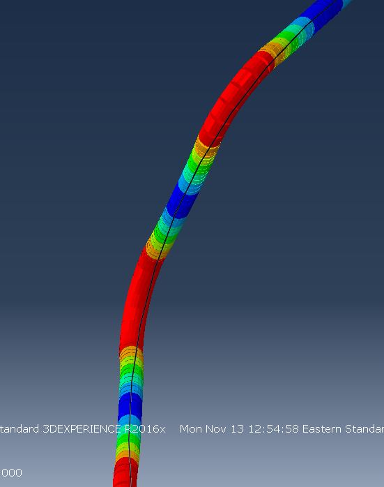
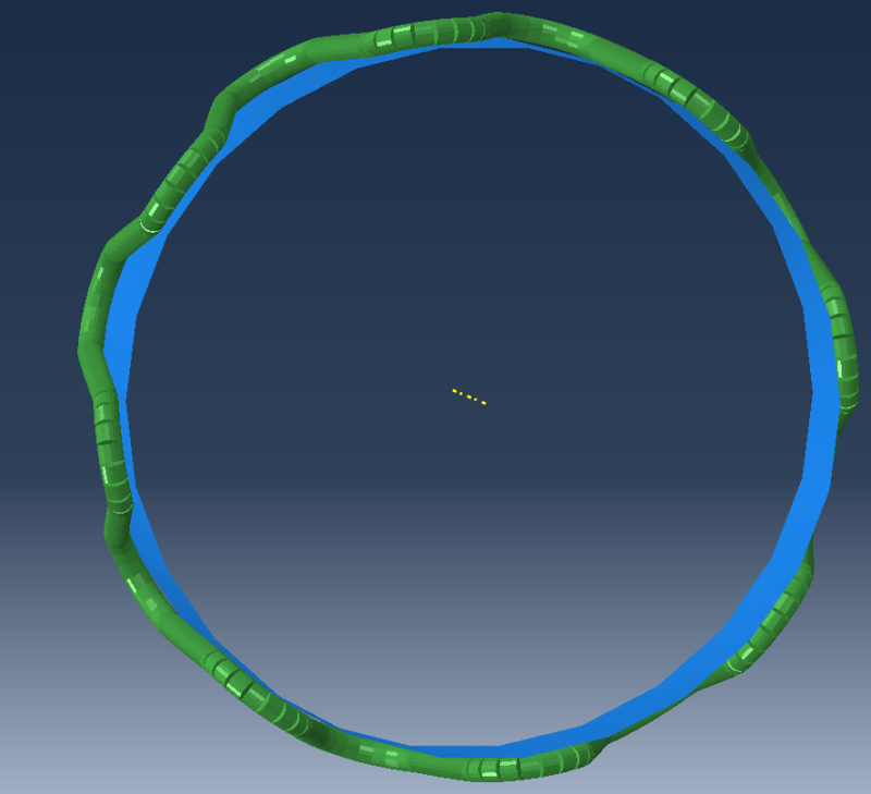
I'm having some difficulty defining contact/interaction between my stent and expansion cylinder (wire stent). I'm not getting what I'm expecting from my results. It is running to completion without errors, but when viewing the results, it looks like my surface is interacting with the actual nodes/elements of the wire rather than the surface of the section. I think this has something to do with an interaction definition, but I don't see how. I think I might see how it's done in Abaqus Explicit with general contact, but I'm using standard and it doesn't appear to be the same.

Any thoughts?
stentBegin_spzbg4.png

stentEnd_vtbvzv.png
 
Replies continue below

Recommended for you

Hi ryan,

I think, at the first photo, your blue part is shell and green part is beam. (Is that true?)

Are you expecting your blue part (which is shell) be interact with your green part's imaginary outer surface (which is beam)?

I don't think it is possible for the beam sections. I suppose that it is only valid for sheel sections to interact even if there is clerence between the surfaces.

Anybody else?
 
Yes, you are correct on shell and beam. You also assumed the correct interaction (blue interact with imaginary outer surface).

Is it just not possible with standard? I have an explicit example which I followed (but changed to standard), which when solved in explicit does have the offset. I do not believe there is anything like an offset defined - just "general contact (explicit)". I had assumed it was in this definition where the interaction with the imaginary surface happened.

Maybe I just have to calculate and take into account the radius of the wire for sizing my expander?

 
I think there may be something like that;

In the model which you followed, I think there may be a modelling tecnique like that;

1- Analist may have modelled the shell and wire with the clearance between them.
2- The clearence equals the half of the shell thickness. (I suppose that he defined the shell thickness from the middle surface) .
3- Before the analysis, he deactivated "exclude shell element thickness" in the contact properties.
 
Status
Not open for further replies.

Part and Inventory Search

Sponsor