Continue to Site

Eng-Tips is the largest engineering community on the Internet

Intelligent Work Forums for Engineering Professionals

  • Congratulations waross on being selected by the Eng-Tips community for having the most helpful posts in the forums last week. Way to Go!

Strand7 help - Global Stiffness Matrix Singular error

Status
Not open for further replies.

Gavla

Structural
Dec 15, 2022
18
Hello,
I have read a number of posts regarding this error, noe of which have helped me to ge this to run. Mine is a simply supported beam in three point bending, though the cross section conssits of three SHS stacked with plates top and bottom (a double web i-beam of sorts). Is anybody able to take a look and give me some advice as to how i can get it running?

Thanks
Gavin
 
 https://files.engineering.com/getfile.aspx?folder=2c28c1e4-b305-4173-a33e-2e41928cda3b&file=Wagner_3-100x5.2_SHS_plus_2-300x6.4pt.st7
Replies continue below

Recommended for you

The problem with your brick model was the material properties. You had the E value in one direction set very low, which was generating a Poisson's Ratio of more than 1, which it doesn't seem to like. I changed all the 2400 MPa values to 24000 and after that the analysis ran with no warnings, but check all the values are correct for your material.

Did you have a reason for using orthotropic properties rather than isotropic? Also unless you have specific properties it is safest to import the standard typical properties for the material you are using.

The density at 2000 kg/mm^3 was also a little on the high side! You didn't have gravity set in your loading, so it wouldn't affect the results, but its best to make sure units are consistent in your model, in case you use gravity loading later.

Doug Jenkins
Interactive Design Services
 
Thanks for looking at that Doug.

The material I am investigating is Glass Fibre Reinforced Polymer (if interested have a look at Wagners CFT webpage, based in Toowoomba Australia)

Ideally I would be modelling it using the correct ply layups that I know you can do in Strand, however, I do not have this info from the manufacturer so am modelling it as orthotropic, as the material does have different properties in different directions. I know also that this approach can be accptable for what I am trying to do, which is some low level deflection and buckling checks. I think my two plate models for the beams sections are working ok now in this regard. I regret wasting so much time over the last few days in hindsight, but I have learnt alot over the last week, so thank you for your help also.

At the risk of stretching the friendship, could I please ask some questions on the attached. It is a two bolt bolted connection (also using GFRP). I have built the model and it runs okay I think. I have the Bolted Joints Webnote for this one which helps.

Firslty, on the Webnote page 22, I am struggling to understand instructions at mid page to create the lateral connections for the bolt head and washer. It states to select rigid links around bolt hole (ok), and use Tools/Convert/Beams to/from links. However when i select this option, there is no option to define a particular target property as it suggest. Also it does not say what the target property is, though think it is supposed to be a contact point beam proprty. Also the intersect all beams to connect the new contact elements to the bolt instruction is not very clear. I abandoned making this model as couldnt understand the instructions.

Secondly, for the attached model, I can view the plate contour stress results, but am not confident with the numbers I am looking at. I need to assess the bolt bearing. Is this possible with this model? Also, I would like to understand what result will show the tension loads across the plate? I understand that the in-plane axis for the plates is x & y, so do i need to look at the xx results, yy results or the xy results?

Thanks for your help.

Gavin

 
 https://files.engineering.com/getfile.aspx?folder=bd98064f-4934-4b02-9e7d-040b67ab84ea&file=W4_tension_plate_2_BOLTS_edge_load.st7
Quick question - I ran the model attached in the linear static solver and got the warning:

*WARNING[ 71]:Nonlinear behaviour of contact cannot be predicted with a linear solution.
Use Nonlinear Static solver to consider nonlinear contact behaviour.

Did you run with the linear or non-linear solver.

I'll get back to you on the other questions.


Doug Jenkins
Interactive Design Services
 
Hi Doug,

I ran it with the non-linear solver, which took a long time actually. It is suggested in the Webnote and also I wanted to try and see if I could try and analyse with node increments, to produce some sort of load capacity graph that will tell me the load at which it fails (by incremently increasing the pressure and graphing this against a capcity). However it takes too long and do not think I have time for this now.

Honestly, I have no realy clue what I am doing with the non-linear solver and how to graph results and do not have the Webnotes. I think now i need to just be able to apply an axial plate edge pressure that i calcuate from an axial load / plate x-sect area, run the linear analysis and extract the tensile pressure and bearing pressure with some confidence, as I mention above.

Essentially what i trying to achieve is to replicate a numerical tension and bearing capacity calculation that i have completed by hand in Strand.

Regards

Gavin

 
Gavin - the trouble is, if you use the linear solver the contact elements won't work properly. You don't need a huge number of stages with the non-linear solver, it should work OK with just 1. The applied load will be the load defined in the model x the factor defined in the solver, so you can set the final load factor in Increment 1, and delete all the rest.

I'll try and have a look at your other questions tomorrow.

Doug Jenkins
Interactive Design Services
 
Thanks Doug, okay will try that. One question on that though, if I go into the load increments there is a load case and a freedom case...do i set the increment to just one and put a factor of 1 in for both cases and run like that? I am not across what the freedom case is?
 
In general you just need to make sure the freedom case(s) you want is/are active. Factors on the freedom cases only make a difference if you have one or more nodes with a specified deflection or rotation. In that case the deflections will be factored but any other restrained freedom will have zero deflection/rotation, regardless of any factor specified for that freedom case.

Doug Jenkins
Interactive Design Services
 
Hi Doug,

I have actioned your comments and re-run the model with only one load factor. Please find attached.

As asked above, I can view the plate contour stress results, but would like clarity on how to view the tensile and bolt bearing forces (is this possible in this model?). I would like to understand what result will show the tension loads across the plate, as I understand the in-plane axis for the plates is x & y, so do the xx results, yy results or the xy results showe these stresses?

Thank you!

Gavin
 
 https://files.engineering.com/getfile.aspx?folder=d73703c4-48ce-44a4-a6d6-70531ddce483&file=W4_tension_plate_2_BOLTS_11.92MPa_edge_load_RESULTS.st7
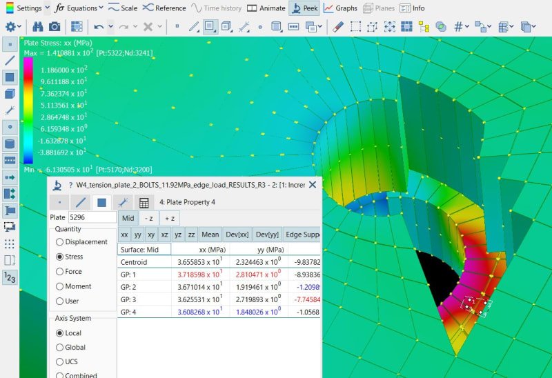
Gavin - I have attached a screen-shot of results from your file. I am using Rel. 3, so some things will look a little different in your versionm but the important things should be the same:

Plate_FEA1_bqjyag.jpg


The main things to note are:
1. Set the plate display to "solid" so they look like brick elements.
2. You can set selected elements to not display, or alternatively set only selected elements to display, so you can make elements transparent that would otherwise hide the elements you are interested in.
3. You can also hide or display selected properties, or assign elements to different groups, that can be displayed or hidden.
4. The "peek" tool gives you detailed results for a selected element.
5. You can also select one or more elements, then select "display selected elements only" in the text based results listing view.

Regarding the validity of the results you are getting, analysis of bolts in steel structures is really outside my expertise. If you have specific questions it would probably be best to start a new thread in an FEA forum, not referring to a specific analysis package, which should get more response from others.

If you have any other Strand7 specific questions, feel free to post here and I will be happy to have a look.


Doug Jenkins
Interactive Design Services
 
Thank you very much for your help Doug.
 
Status
Not open for further replies.

Part and Inventory Search

Sponsor