Eng-Tips is the largest engineering community on the Internet

Intelligent Work Forums for Engineering Professionals

Strengthening an Existing Truss 1

Status
Not open for further replies.

canstruct12

Structural
Dec 18, 2018
26
0
0
US
Hello All,

Canadian structural engineer here. I am currently exploring options to add section capacity to an existing truss. The work would be required to be done in place at ~30feet from the slab below.

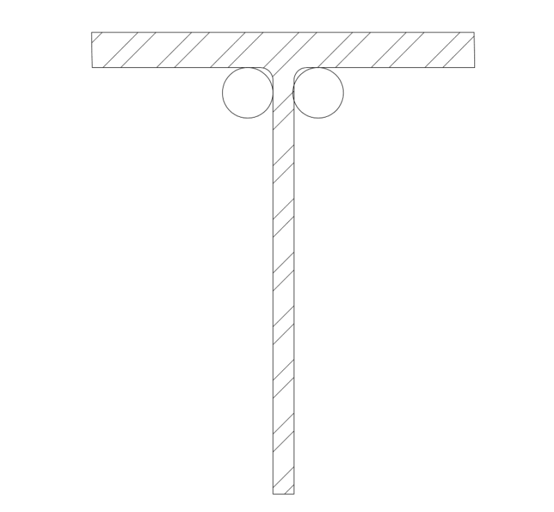
The top and bottom chords are T-Sections
Truss Span: 50 feet
Truss Depth: 5 feet
Top Chord: ST 7 WF 30.5
Bottom Chord ST 7 WF 26.5
Web Members: Various Star-Arranged Double Angle Sections (with a single midspan interconnector) 2 - L 3.5 x 3.5 x 5/16 at the truss end to 2 - L 2 x 2 x 1/4 at the truss middle

20210805_005944_znxnd4.jpg


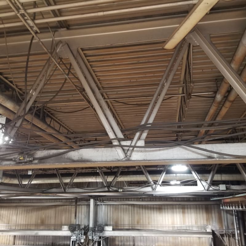
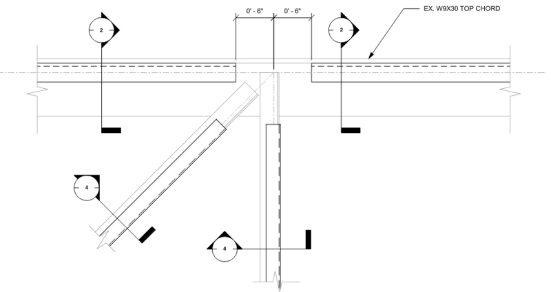
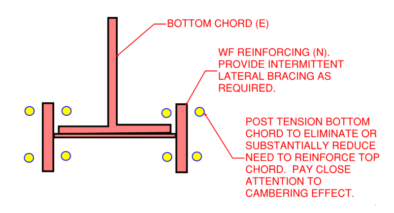
The truss top chord is proving to be the most difficult to determine a method. It is not possible to add to the top of the T-section without removing the roof and OWSJ. The web members make adding continuous sections to the side or bottom of the T not possible.
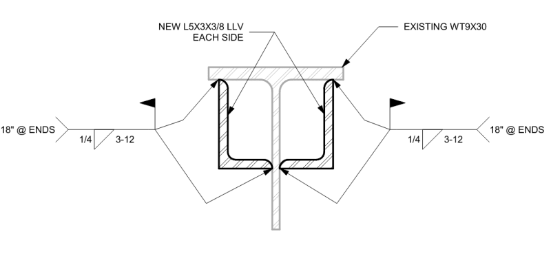
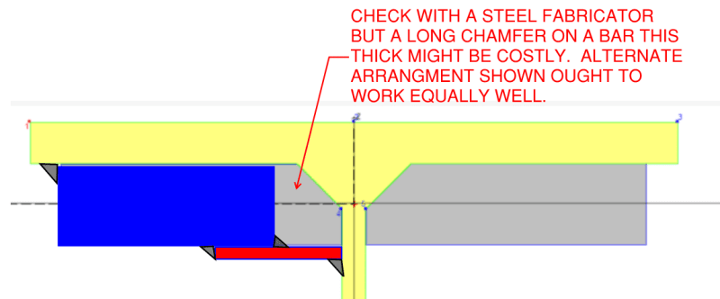
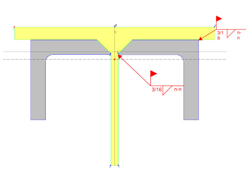
Currently exploring welding angles (L4x4x3/4) to the underside of the top chord T. This seems like the only viable option that I can see, due to the physical limitations and interferences. The angle size was chosen to add sufficient area to increase capacity to the required amount, as well fit over the web members and allow weld between the underside of the t-section and angle at the outside.

Capture_3_tg5bzo.png


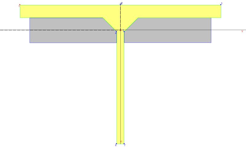
I am using STAAD Section wizard to determine section properties (STAAD does not give an entirely accurate visual representation of the flange to web radius transition) , then using these to verify sufficient capacity based on applicable CISC S16-19 Standard.

Capture_2_tvf4pq.png


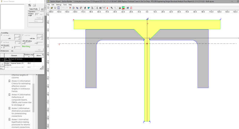
My only concern with this is at the radius transition between the Flange and Web will require chamfering the angle to fit at this location. I was planning to use a 1/4" intermittent weld at 3"-6", and am not sure if there would be enough meat on the angle to effectively weld if it is chamfered to fit.

Any feedback would be appreciated.
 
Replies continue below

Recommended for you

Rather than angle, can you weld round BAR stock in the T fillets? intermittent fillet welds and weld at end... also bar stock for reinforcing the webs if necessary.

From my notes:

-FOR INTERMITTENT WELDS, LENGTH SHALL NOT BE LESS THAN THE GREATER OF 4 TIMES THE WELD SIZE OR 40MM (1-1/2”). FOR COMPRESSION MEMBERS, THE MAX CLEAR SPACING BETWEEN WELDS SHALL NOT EXCEED 12”. FOR TENSION MEMBERS, THE MAX CLEAR SPACING BETWEEN WELDS SHALL NOT EXCEED 18” (CSA W59 11.4.13.2).


Eng-Tips_cbppdy.png


Rather than think climate change and the corona virus as science, think of it as the wrath of God. Feel any better?

-Dik
 
I would be more comfortable with a detail similar to below:
truss_reinf_vphze4.png


I have seen this detail used successfully in the past and I believe addresses some of your concerns.

You may want to look into having the top chord reinf be discontinuous at panel points to avoid fouling the web member connections, similar to this detail:
truss_reinf2_zpzqsh.png


Although this definitely complicates the buckling analysis of the chord.
 
in case you didn't already have this:
SJI Technical Digest No. 12
Evaluation and Modification of Open Web Steel Joists and Joist Girders
 
dik: We did look at this as an option initially, the round bar needed would be ~3" diameter and would not be able to be continuous at the web members. That is an excellent point regarding the intermittent welding.

lexeng18: The first detail (with inverted angles), there would still be the same interference with the web members. The second detail, would there not be a concern about having a discontinuity in the reinforcement and having a portion without adding capacity?

kipfoot: I do not have that already, I will look for that document tonight.

I did find the following video:
[URL unfurl="true"]https://csengineermag.com/evaluation-and-modification-of-open-web-steel-joists-part-i/[/url]


Thanks everyone for your responses, very much appreciated.
 
The round bar is common reinforcing for trusses...

Rather than think climate change and the corona virus as science, think of it as the wrath of God. Feel any better?

-Dik
 
How much area are you adding? the fillet radius shouldn't be an issue... you can use ASTM 1554 in grade 55S1... can you use flat BAR stock with 1 corner milled off (expensive) to accommodate the fillet... flat bar centroid is closer to the outside fibre and away from the ends of the web diagonals.

Rather than think climate change and the corona virus as science, think of it as the wrath of God. Feel any better?

-Dik
 
Dik: Yes, agreed, the round bar was my initial thought. I need to add ~7000 mm2.

Looking at this now, I should be able to use 1-1/4" x 4-1/4" flat bar to get the necessary area, and this should be able to be ran continuously without interfering with the web member connections.

Capture_4_w1cocq.png
 
If I'm reading this right, you're trying to double the area of top chord? I would be considering trying to come up with a sistering solution or adding additional joists rather than trying to reinforce the truss that much. Do you have a reliable way to reinforce the web members? What about their connections to the top and bottom chords, especially with the reduced length available from the chord reinforcing?

Go Bucks!
 
Straub46: Correct, I need to more than double the area.

This is a truss which forms part of a mill bent in an open shop. These bents occur at 20' intervals. It is not feasible to add more intermediate bents or trusses.

Web members are star arranged angles and have an available 10mm spacing between angles. I believe it will be possible to add a 10mm plate between the angles, additional connection capacity can be added by lapping and welding the 10mm plate with an additional plate.

This is all very preliminary.
 
What grade of steel? Can you use 60 Grade weldable rebar? I think rebar is the cheapest steel per pound...

Rather than think climate change and the corona virus as science, think of it as the wrath of God. Feel any better?

-Dik
 
canstruct12 said:
The second detail, would there not be a concern about having a discontinuity in the reinforcement and having a portion without adding capacity?

It depends. If you need to be able to mobilize the full yield stress of your top chord then, yeah, it's likely a problem. However, chord design is often not governed by gross cross section yield but, rather, things like buckling. Where that is the case, it may well be possible for the chord reinforcing to be discontinuous.

canstruct12 said:
Straub46: Correct, I need to more than double the area.

Similar to straub46, I would expect a truss requiring that much chord reinforcement to be failing the webs and the web connections as well. I think that it would be useful here for us to know:

1) What new loading condition has brought about this reinforcing requirement and;

2) What failure mode governs the chord design? Yielding? Buckling? Torsional buckling? Truss deflection?

The sketch below shows some comments that I have with respect to your flat plate reinforcing scheme.

c01_h95yqc.png
 
kootk said:
1) What new loading condition has brought about this reinforcing requirement and;

2) What failure mode governs the chord design? Yielding? Buckling? Torsional buckling? Truss deflection?

Response to the above questions:

1) The building was designed and constructed ~60 years ago. At that time the code which governed design did not account for any drift loads. The building where these trusses are located shares a common wall with another building with a ~50ft higher roof elevation with a ~80000ft2 plan area, which creates a large drift load on the building I am analyzing. They are replacing an overhead crane which is supported off the roof trusses and wanted the building structure analyzed.

2) I was able to replicate the original truss analysis, which is a simple truss analysis (method of joints). From this the failure mode is torsional buckling.


Thanks for the sketch, I will have to look at the section properties to ensure that it will work.

While torsional buckling is the govern failure mode, the sections between OWSJ are relatively short (5 ft), so the torsional buckling capacity is not much less than the full yield strength, So I would need close to the full section area to account for the additional forces.
 
Mostly good ideas here. Flat bar or your original toe down angle seem sensible. I'll reiterate other peoples comments you need to avoid chamfering the plate or angle that is a nightmare for cost. Also if you are doing toe down angle I'd used unequal angle to give better access for the weld.

Kootk's idea seems the easiest for site welding. It needs more welding overall but half of it can be done in the fabrication shop which will significantly reduce costs.
 
See the sketch below for another reinforcing alternative. It's a bit exotic but, then, drastic times call for drastic measures.

A mentor of mine used to tell me that, beyond a certain point, it's prudent to think of these things not so much as reinforcement exercises but, rather, using the existing truss as essentially scaffolding to support a new truss. At the level of reinforcing that you're contemplating, I'd say that you're drifting into that territory.

c01_grip6f.png
 
There are possibilities outside the existing roof:

1. Build new joists or trusses with steel deck to carry the drifting snow.

2. Build open trusses without deck, using hangers as required to assist existing trusses.

BA
 
I thought I would just add that I concur with KootK and human909 that chamfering a long, thick steel plate like that is a hell of a cost especially if you want any kind of precision.

Also, glad to see KootK back in the game! I was starting to get afraid you had left us for greener pastures.

CWB (W47.1) Div 1 Fabricator
Temporary Works Design
 
I'm waiting for a reply from a local fabricator, that I do work for, to see what's up... decades back when I worked at Dominion Bridge in the summers, it was simply a matter of milling/scraping off a corner; it was a simple process... we'll see what is done today. No real precision is needed. What yield strength was the added steel?

Rather than think climate change and the corona virus as science, think of it as the wrath of God. Feel any better?

-Dik
 
Status
Not open for further replies.
Back
Top