Eng-Tips is the largest engineering community on the Internet

Intelligent Work Forums for Engineering Professionals

Stress Concentration in D-Profile Shaft 3

Status
Not open for further replies.

sheafromme

Mechanical
May 1, 2020
25
0
0
US
Hello,
I'm having trouble determining how to account for stress concentrations at the root of the flat on a motor shaft due to overhung radial loading. I inherited a motor/pulley assembly that has an propensity for the shaft to snap off right at where it transitions from a D-shape to circular cross section. The pulley pictured below has a belt on it that applies the loading.
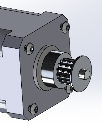
Mot_mubjgb.png


There is not a fillet where the shaft changes profile
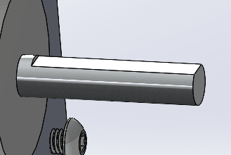
sh_fkrjeu.png


I've looked through most of the resources I have here and I can't seem to find anything that addresses this particular situation. It' probably because it's not a great design...

So, I was just wondering how to properly calculate the fatigue life or at least how to account for the huge stress concentrations at that transition point due to bending.
Thank you!
-Shea
 
Replies continue below

Recommended for you

If it is sharp enough corner it's likely to be 10X to 100X the nominal stress for a shaft that diameter. Most applications avoid the situation rather than accounting for it. You may be able to determine how many cycles the shaft is getting based on time in service and utilization.

If you have to use that motor, rework the shaft to smooth the transition.
 
Flipping the pulley to reduce the overhang and being sure the belt is not over- tensioned can help too.

If the belt pull from transmitted torque looks to be a problem, increasing both pulley sizes to maintain the ratio reduces the working belt tension

Like others said, a sharp corner by itself is a big problem.

Got pictures of some failed shafts?
Stuff like the fracture initiation point, the fracture surfaces, setscrew bitemarks, and fretting from pulley micromotions can be valuable forensic clues.
 
Who is the motor manufacturer - does their literature list allowable overhung load? That shaft may be intended for direct-coupled use where the shaft slips into a quill on a reducer, thus transmitting only a torsional moment, no bending moment. Even if you reduce the load enough to stop breaking shafts, you may still be overloading the shaft bearing and just move down the line of failure points. You really need to stick with rated loads.
 
Thinking out loud here. Crankshafts on engines often have undercut fillets. Perhaps you could use a small file to undercut the sharp edge a bit. The loss in cross section area may be offset by the reduction in stress concentration. I don't know if this thought is true, the undercut fillets on crankshafts are rolled, not cut, so they contributed to the strength and reduce stress concentration.

 
Shea said:
So, I was just wondering how to properly calculate the fatigue life or at least how to account for the huge stress concentrations at that transition point due to bending.

Why? What's the point?

It seems like you already have a history of in-service failures, so you must already know the fatigue life, right?

What value does a calculation add at this point?

Doesn't your goal need to be a new design?

Timing belt pulleys with QD or Taper-loc hubs are cheap and easy to find.
 
Your belt is too tight. Or the orientation of the pulley creates too much overhung load. But I would go with excessive belt tightness. Some technicians believe a synchronous belt has to sing a high-C or its not tight enough. Wrong!!

Yes, the sharp corner of the flat is a contributing factor, but the manufacturer designed and built that motor to run with the correct range of belt tightness without failing. Loosen that belt, or flip the pulley around.
 
I'd combine your service experience with a fatigue test program ... to identify if belt tension is critical (which it likely is)

Loading as well as geometry is critical for fatigue. I'll assume you're the motor manufacturer or that the motor design is fixed.

What service experience do you have ? time to failure (since purchase) ? running time (with known speed) ? non-failures ??

A test program would allow you to determine if the motor fails with the specified belt tension, and so failures are due to improper installation (an important point to mgmt).

What testing did you do with the initial design ? what fatigue analysis ?? or did you expect it'll work ok ??

How easy is it to replace the shaft ? Offer a rebuild service, save the customer from unscheduled downtime ? make a little money on the side ??

Would this feature be much different to a shoulder ? Thinking about, yes, maybe it is ... or consider as many different shoulders, due to different positions along the flat (you have a deep shoulder on the CL and almost no shoulder at the face of the shaft, all with the same fillet rad ... different geometries, different Kt)

"Hoffen wir mal, dass alles gut geht !"
General Paulus, Nov 1942, outside Stalingrad after the launch of Operation Uranus.
 
Hi sheafromme

If the motor complete with shaft is a bought out part then the manufacturer of the complete unit should be able to provide what maximum overhung loads can be applied when the motor is running. I suggest that you try to obtain that information and then compare that with your predictive overhung load plus whatever the belt tension is, obtaining that info could save you a lot of time.
Do you have any photos of the failed shafts? Some pictures would help us to help you further.

“Do not worry about your problems with mathematics, I assure you mine are far greater.” Albert Einstein
 
@3DDave Thank you for the response! That's what I feared...definitely makes sense about just avoiding the situation altogether but unfortunately I'm a bit backed into a corner in that I have a relatively narrow scope of allowable action on this. I could definitely see if the supplier could smooth that shaft transition then, thank you for the suggestion!
 
@Tmoose
I actually think I may go with the flipped pulley suggestion you had, it would allow the flat transition to be within the pulley instead. I already developed a tensioning procedure that prevents over-tensioning (ostensibly) but there are hundreds in the field already...
I'm thinking it's the overhung load not torque; as far as I can calculate from my tension recommendations there are many with the load over the mfg recs.
Here's a picture of the shaft, it's right at the transition point:
broken_shaft_qkxo0h.png
 
@dvd Thanks for the response! My spec for the tension is now below the mfg allowable overhung load [dazed] unfortunately there are a lot in the field that already got delivered apparently.
I think you may be onto something with the motor use-case; the literature seems to reflect that at least from what I've seen.
 
@TugboatEng Thank you for the input and resource, I think the manufacturer could do something to help out with the undercut; I'll reach out to them about it!
 
@MintJulep It's partially my own interest to see if I can make theoretical converge with the field results and also to fulfill a requirement for the report haha!
 
@Jboggs Thanks for your response, I have since updated the tensioning procedure for exactly the reasons you laid out [hourglass] I think I may end up flipping the pulley around because otherwise it has to rest right at that flat transition due to other assembly constraints.
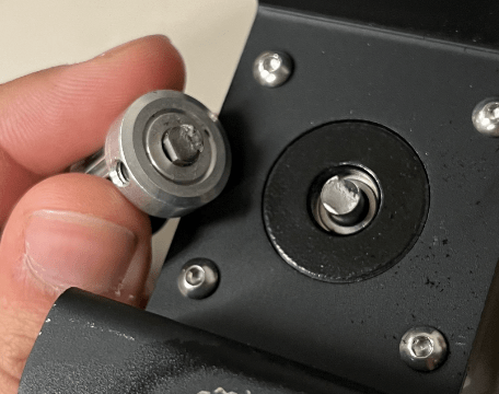
 
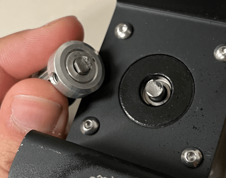
@rb1957 Definitely makes sense, I'm almost entirely certain that the belt tension is the culprit but not entirely sure in what way it causes failure besides excessive stress concentration at the flat to shaft transition.
Motor design and some other parameters are fixed unfortunately. This is also not my design so I'm sort of trying to piece together the process as I go but it's a bit opaque. I'm sort of retroactively doing the analysis to at least piece together what happened and perhaps to inform future design of related systems. Thanks for the food for thought!
 
@desertfox Thank you for the response! I did find that the overhung load was over mfg specs and have already implemented a better tensioning procedure. Unfortunately, some failed units were below the overhung load spec and there are also a lot of these in the field already. I inherited this issue/design so it's been a bit of detective work to figure out exactly what assumptions were made. Here's a picture if you want to see more closely.
broken_shaft_oundd8.png
 
Hi sheafromme

Thanks for the response and photographs and it certainly looks like a fatigue failure, have a look at this site giving photos of failed shaft and their causes.


I appreciate that the shaft isn’t completely round and that there will be a stress concentration where the flat is, however if you ignore the flat on the shaft for the sake of a calculation and assume that shaft is completely round you can then calculate the maximum principle stresses using the mohr circle. The shaft is failing under fatigue however the maximum principle tensile stress causing the failure is a combination of the overhung load and the motor torsion and not one or the other.
Google mohr stress circle for shafts under torsion and bending loads.

“Do not worry about your problems with mathematics, I assure you mine are far greater.” Albert Einstein
 
I have a suggestion for a fix:

I can see the inner race of the motor bearing in your picture. Manufacture a spacer that slides over the shaft and rear against the bearing inner race.

The spacer should be long enough to extend beyond the step transition between D and round sections. A few thousand of an inch should be sufficient without negatively impacting belt alignment.

Butt the pulley firmly against the spacer prior to tightening the set screw.

Ideally, some of the bending forces will be transfered by the spacer so less will be seen by the shaft.

Your success will depend greatly on how firmly you can butt the two together. Perhaps a Belleville spring arrangement will make assembly more forgiving?
 
won't belt tension create bending at the section ? so flipping the pulley makes the off-set less, yes?

"Hoffen wir mal, dass alles gut geht !"
General Paulus, Nov 1942, outside Stalingrad after the launch of Operation Uranus.
 
Status
Not open for further replies.
Back
Top