Eng-Tips is the largest engineering community on the Internet

Intelligent Work Forums for Engineering Professionals

Structural integrity of a welded steel stand for two condenser units 8

Status
Not open for further replies.

Parker87

Computer
Aug 4, 2020
23
0
0
MK
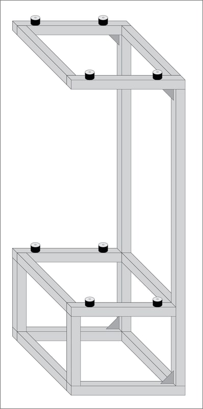
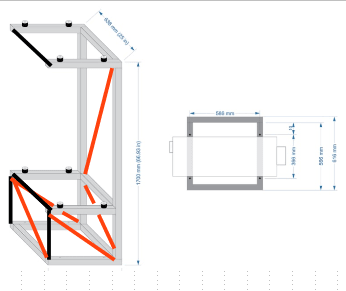
I've recently bought two mini split heat pumps and want to build a stand to hold the outdoor units. I would like to obtain an E-shaped cantilever structure but am unable to determine whether the beams will hold the units safely in place without adding some form of additional support (e.g. diagonal braces).

LG_U24_Stand_-_P_T_n5so5h.jpg


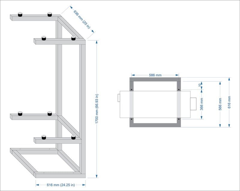
I plan to use 50mm x 50mm x 2mm (2" x 2" x 14ga) square steel tubes which are going to be welded together as shown in the drawing above. The small cylindrical shapes are rubber-metal mounts that will go underneath the condenser units to prevent vibrations from being transferred to the steel frame. I might also use some larger rubber-metal buffers to decouple the stand from the concrete foundation on which it will be mounted, so any unmitigated vibrations don't find their way into the nearby walls of the house.

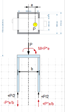
The weight of the outdoor units is 43kg (95lb) each, and the way this weight is distributed on each corner is shown on page 11 of LG's product data book (i.e. page 13 of the PDF) linked below.


Since this stand is only going to be secured to the ground (and not to a wall), my main concern is stability, i.e., supporting the weight and stress from the two condensers without bending, breaking, or tipping over, while enduring the fluctuating weather conditions.

Any thoughts or advice would be greatly appreciated. 
 
Replies continue below

Recommended for you

Without looking into any detail, I suggest to locate a solid wall to provide lateral stability, tipping/roll over is the main concern. Do you know the design wind speed for the local, and are you in an earthquake zone, which one (A thru E).
 
Well, if I was building it I would add some angle braces or gussets. Cantilevering the arms is a bad idea. Same for the base to side rails. And I would attach the units to the frame, not just sit them on the bumpers.
 
And in the engineers with hobbies forum.....

Now double posting really isn't allowed so please choose one forum or the other.

Remember - More details = better answers
Also: If you get a response it's polite to respond to it.
 
If I am doing it, I'll add quite a few members as shown in sketch below (Black - HSS, Red - rod/plate/HSS diagonal). The upper cantilevers may require kickers too. Do you think you can handle all calculation required? Although it is small, the concept is the same as a building frame.

image_bzkhnn.png
 
Sorry for the double post, that was a mistake. I wanted to delete the other one but it's just now that I am noticing the "delete" button at the bottom of the OP. I want to respond to the replies I got there, too, so I will replace the content of the OP with a link to this thread instead of deleting it. Or if a moderator can merge the replies into a single thread (this one) and delete the other one, that would be awesome.

I am busy now, but will post more later. Thank you all for your replies.
 
I was thinking a space frame to hold a person's weight:) But at least attach it to a wall, or something solid.

Watch out, the weight is off the center of geometry. You need to ensure later stability (leaning tendency).
 
My greatest concern is with the welding of 14 ga. material. It is easy to burn through. Here are a couple of videos about stick welding thin gauge steel.


Good welds are difficult to achieve if the members have the same width. As Dik said, it may be better to use 1.5" HSS members for the horizontal arms, but the welding is still tricky and you can't develop the full strength of the cantilevered arm when welding across the wall of the 2x2 HSS. The load is fairly light, so it may be strong enough, but would need to do a yield line analysis to prove it.

Also,the base needs to be tied down so that the whole thing can't blow over in a strong wind.

BA
 
LittleInch said:
What is it sitting on?
Concrete foundation surrounding a brick veneer house.

LittleInch said:
Why two one on top of another?
Because I don't have sufficient space to put them side by side in the location I want to utilize. Clearance requirements suggest a lot of open space around them — they will have to be placed at least 1 meter apart and be clear of any surrounding obstacles.

SWComposites said:
And I would attach the units to the frame, not just sit them on the bumpers.
Of course I will do that. It will look something like this (the one on the left), except I'll need to use longer bolts on the bottom to pierce through the steel tubes and come out from below.

retired13 said:
Do you know the design wind speed for the local, and are you in an earthquake zone, which one (A thru E).
Not sure. I think I'm in the "moderate" seismic hazard zone. There's been a few short bursts of unusually strong winds over the past two years or so.

dik said:
retired... the framing is robust and the loads are relatively small.
This is why I quoted the weight and posted the link to the technical specs. :) I would like to keep the design as minimalist as possible, but if attaching a few braces or gussets in the right (or most critical) places would strengthen the build significantly, I wouldn't mind doing it.

retired13 said:
Watch out, the weight is off the center of geometry. You need to ensure later stability (leaning tendency).
Yeah, most of the weight (around 72% if I'm reading the specs correctly) falls on the right mounting brackets, and I have no idea whether and how to address this.


Parker,

On top of machine weight, you need gather the wind load, snow load and seismic design coefficients, which will be used for frame member sizing, connection design, and fastening of the whole unit.

The off center weight creates a moment (rotation) about the center of the frame, which will resolve into a couple at the support legs. The net support reaction is the sum of effect of the weight plus the couple. See sketch below (Red - moment, force couple).

image_xmywvf.png
 
BART:

With the weld, you can develop about 80% of a CJP if properly done... about 3x what is needed, if prelim calcs are OK. Didn't need to complicate the welding by using fillet and flare bevel welds, therefore reduced dimensions of the horiz and vert tubing. I'd prefer to see 1/8" wall thickness, easier and safer weld and not much more costly. He should still add mounting tabs at the bottom and use TEKS 3 or TEKS 5 for mounting the equipment to the 'arms'. A vibration isolator can be placed between the equipment and the HSS. He really needs to check the design... or have a real engineer do it.

Also tie the top to keep the frame from translating.

Dik
 
Dik, the vibration isolators have independent top and bottom threading so you can't really screw through them:
Considering the specifics of the weight load distribution, would you still say there's no need to put any diagonal braces or gussets?

dik said:
He should still add mounting tabs at the bottom

What's the reason for avoiding fastening through the steel tube? I dislike the idea of using mounting tabs at the bottom because of the off-center positioning of the vibration pads. More than half of their "supporting" surface will inevitably stay clear (no matter which direction the tabs are facing) and the tubes will end up resting only on the remaining portion of the pads.
 
Following some of the suggestions provided in this and the other thread, I have updated my design to the following:

LG_U24_Stand_-_P_-_v2_cxg88r.jpg


Not sure if this would be the right type (or size) of gussets to use, so if anyone has a different/better idea, please let me know.
 
Those gussets are installed as what I refer to as "can opener." The sharp ends are in the middle of the thin wall. In this case they perform no function as the rest of the structure is stiffer, but I've seen similar gussets just punch through.

Typical gussets would be cutting tubing to fit so the flat side walls have structural continuity.

If you like, I'd recommend the James F. Lincoln Arc Welding Foundation book on Design of Welded Structures. It's $25, so it's a good deal, probably the best ever for engineering.

I'd rather not do a full analysis or explain what the book details vs the $25 book which does a more complete job. The target for the book is people in your situation re weldments.
 
Status
Not open for further replies.
Back
Top