Continue to Site

Eng-Tips is the largest engineering community on the Internet

Intelligent Work Forums for Engineering Professionals

  • Congratulations KootK on being selected by the Eng-Tips community for having the most helpful posts in the forums last week. Way to Go!

Structural Wall" definition AS3600-2018 3

Status
Not open for further replies.

QSIIN

Structural
Apr 21, 2013
50
Hi all,

Just want to get some opinions on the changes to "structural walls" in new 2018 AS3600.

Section 14.2.10 defines a structural Wall as:
"Wall (either load bearing or non-loadbearing) connected to floor diaphragms that attracts horizontal earthquake and wind design actions".

At what point is a wall considered to "attract" EQ and wind actions? If we're talking about "gravity only" walls in a structure that has a stiff core and other lateral resisting shear walls, these elements might attract just a fraction of lateral actions - but they still attract some as they are connected to the diaphragm, but can you argue they aren't part of the lateral system and therefore do not need to comply with section 14, save for drift consideration? Or does pretty much any vertical compression element that is not explicitly a "column" now count as a "structural Wall" and must comply with 14.4.4.3?

Subject to the above, if you have "gravity only" walls, to section 11 in lieu of columns, but a ductile core, is the whole structure ductile or non-ductile? Even if the walls aren't part of the primary lateral system?

Section 11.5.2(b) limitations for the simplified wall design:
"Not to be constructed on sites with soil classification of De or Ee, AND where subjected to earthquake design actions"

Are those two limits mutually exclusive? Can you have walls that are constructed on De soil but not subject to EQ? Is that even possible? Can you have walls on Ce soil classification that are subjected EQ actions?


I think both these points are too vague and not explicit enough in their intent, and will be exploited to get away with using simplified wall deisgn in excess and to continue ignoring seismic design.

I understand the code is not meant to be a detailed how-to guide and their must be engineering judgement, but from my experience unless the code says "can do A, cannot do B", option b will be a viable solution for some..


Replies continue below

Recommended for you

QSIIN

I have 3 answers for this, two of which were provided by an Earthquake design specialist and one of which I cannot print here or I might get banned (or threatened again).

My simple reply is

"A non-ductile wall in a ductile frame will not last past the second sway in an earthquake, and therefore will not be a gravity resisting vertical element thereafter."

His further more technical addition to this is

"Structural walls tied to the floors and carrying gravity loads form part of the lateral system and must be treated as such. It is incorrect to assume otherwise. The ductility assumptions for all structural walls need to be consistent across the structure unless a displacement based analysis is used to establish the ductility demand on each wall element for the design event."
 
Most in-situ vertical element within a structure will experience some component of lateral force when subjected to an earthquake (or wind event). Concrete buildings in Australia are likely to have fire stairs and lift cores that act as the primary LFRS. When you perform an analysis in Etabs or similar building analysis package, it is common to reduce the stiffness of slab elements and column elements further than the values given in AS3600 (columns = 0.3 to 0.8 and slabs = 0.4).

In my experience, the common criteria used for engineers to start considering a vertical element as a wall is an aspect ratio of 4:1. Residential buildings tend to have blade columns with vertical element widths generally governed to slot within apartment party walls. I think it is prudent that the engineer considers these as lateral elements for analysis. You may confirm that no additional reinforcement other than the minimum reinforcement required for columns (or wall if forces are small) after considering axial, shear and flexural demands, but this cannot be omitted from the verification process. I'm looking at a model now with a blade columns each with about 1% of the total shear demand on the building from Earthquake. Although small relative to the demand which goes to primary LFRS elements, this shear and flexure must be considered in design.

A site soil classification of D and E prohibits the simplified method of 11.5 for compression force design. Provisions for columns in section 10 must be used for design in this instance including detailing requirement.


rcassar said:
When you perform an analysis in Etabs or similar building analysis package, it is common to reduce the stiffness of slab elements and column elements further than the values given in AS3600 (columns = 0.3 to 0.8 and slabs = 0.4).

Are designers simply using a lower number because they feel like it, or are they doing the required analysis to justify the reduction?

You cannot use less than the cracked inertia, and it is hard to get below .3 on that basis? Technically it should be higher than the cracked value to allow for tension stiffening between the cracks.

 
Hi Rapt,

I was afraid you'd have an answer along those lines, though thank you for the contributions you can give. It's a shame that's how it is. Any chance I can get that third response privately?

The two you've answered are my impressions as well. With the new amendment coming to AS3600, can we expect some rewording of things for better clarification? I think this is important as, unfortunately, EQ analysis and design is brand new to a lot of very experienced engineers.

Regarding cracking of elements, I would think if the member is uncracked then the analysis should be done using gross member stiffnesses, as the code states. Cracking the columns might be conservative for the Core box design, but if you've got 2-3m long blade walls cracked down so the core does the work, you need to first justify how it's cracked, and second think about the consequences of it actually cracking - does the wall fail? The whole building doesn't need to collapse in an EQ for it to be considered failed.
 
The code does not teach earthquake design. Designers need to study earthquake design logic before trying to apply it, and that requires good text books. Agent666 or someone from NZ might be able to help with guidance on sources.

The logic is nothing like what people have gotten away with for wind design previously.

There will be a commentary next year, but designers in Australia are traditionally not taught earthquake design and a lot of the more experienced designers still think in terms of "wind design controlling strength so we will just do that and it will cover everything". Designers need to study and understand earthquake design before they read the code!

RE stiffness, if it is uncracked under full earthquake load (not reduced earthquake design load) then yes, it is uncracked for analysis.

The difference in simple terms with earthquake design as required by AS3600 is you
- determine the earthquake load,
- assume a level of ductility which reduces the earthquake load by a factor
- design for strength based on that reduced load
- detail it based on that assumed ductility

So if the assumed ductility does not match the detailed ductility, when the full earthquake load hits the structure does not have the combination of strength + ductility to survive. It you have assumed moderately ductile, then you have designed assuming an earthquake sway of .67 / 3 of the full sway, so .2233 of the full sway. If the structure is not designed and detailed to handle 4.5 times the sway you have designed for, you are in trouble.
If one or more elements in that structure are not designed and detailed for the full sway, they could lose all gravity load capacity. So even if they are not being expected to resist sway, they will no longer be able to resist gravity loads either (hence my simplified comment in my 1st post). You will then be relying on your Robustness design to hold it up. And not many are doing that properly either. For example, AS3600 section 8 deemed to comply beam reinforcing does not guarantee any level of robustness as it does not require continuous bottom reinforcement. Designers have to work it out for themselves.

The next comeback from someone will be "but we are not paid sufficient fees to do all of that". You already know my response to that so I will not say it again.

 
Even though quite old now, the old Park & Pauley text 'Reinforced Concrete Structures' is a good primer for seismic design (and detailing of concrete structures). These guys were the driving force for adopting the capacity design approaches ingrained in NZ and many international seismic design standards.

But really any half decent text should take you through the basics, I think the issue in Australia is the lack of commentary explaining the 'why' and a lack of people being taught it effectively in universities is a big part of the issue. It's not something new, most Aussie engineers I've worked with over here in NZ have a really hard time picking it up and hence actually being good at it because they weren't even taught the most basic things in university when it comes to ductility and seismic design. You don't know what you don't know..... Stuff that we are force fed from year one at University.....

 
On a related topic AS3600 14.1(b)(ii) states:

Capture_tfsytu.png


Does this mean the entire building needs to use Class E reo, or is it just the lateral load resisting elements (or somewhere in-between)?
 
Hi rapt,

Just following on from the above discussion, I understand that the seismic demand on so called "gravity only" blade walls and columns should not be disregarded in design however negligible it may be, but was wondering if we design and detail the main lateral load resisting elements (cores and shear walls) as limited or moderately ductile, do the "gravity only" blade walls and columns need to also be designed and detailed based on the limited/moderately ductile assumption as well, or do they need to be designed as non-ductile based on the full elastic earthquake load?

Does clause 14.4.4.3 - Axial load limit for elements with u > 1 that are limited/moderately ductile play any role in this determination? The clause appears to imply that if the stress under G+0.3Q in any wall/column exceeds 0.2fc', you cannot proceed based on the limited/moderately ductile assumption and will need to design the wall/column element in question as non-ductile for the full elastic earthquake load. What are your thoughts on this?
 
There is no such thing as a 'gravity only column' in a concrete structure subject to earthquake.

They all go along for the ride from a drift compatibility standpoint. How much curvature a potential yielding region sees in these situations governs how it should be detailed (i.e. what level of ductile detailing is required). I don't have a copy of the 2018 aS standard so cannot answer your direct query, but history tells you assuming gravity only columns is not a wise choice if you want to design for all the possible actions that develop in your columns during an earthquake.

In NZ we went through a period from 1982 to 1995 where some bright spark decided we could classify columns as 'gravity only columns' in our design standard with no consideration of what seismic forces developed as they go along for the ride to the same drift as the main lateral load resisting system. They severely relaxed the detailing requirements with respect to confinement/anti-buckling and shear reinforcement in these sorts of columns (things you generally need to increase the reliability of getting some sufficient ductile response out of your columns). These so called 'non-ductile columns' had some part to play in the two major structures that collapsed in our 2011 Christchurch event, and we've been addressing and strengthening for this condition every since.....
 
Drapes,

Not sure how you read that into it. There are no tricks that I can see in the wording.

Structural wall definition is in 14.2.10. It is very specific. Basically any wall connected to the floor diaphragms that attract horizontal earthquake or wind action.

The clause is simply controlling the wall dimensions for "All Structural Walls" based on the defined loading. A structural wall, whether it be ductile, limited ductile, non-ductile, if it is structural, the axial load stress is limited to this value.

 
Thanks Agent666 and rapt for your feedback.

rapt, the clause does not appear to concern non-ductile walls though, as it only relates to elements with a ductility factor of greater than 1.

Clause_14.4.4.3_s054kk.png


Also, if this clause relates to all structural walls (including columns), it will be very difficult to satisfy this clause for the majority of columns given that they will be attracting very high axial load at the outset due to gravity (even under the seismic weight given by G+0.3Q).

Finally, as I mentioned before, if I designed and detailed my main lateral load resisting elements (core and shear walls) as limited or moderately ductile and there are no issues on that front, but a handful of columns fail to satisfy the above clause, does that mean my initial assumption of taking limited or moderately ductile becomes invalid, and will need to either increase the size or strength of the columns to suit, or resort to designing the whole structure as non-ductile? As you noted in a previous post, "The ductility assumptions for all structural walls need to be consistent across the structure..."
 
You may not be recognising that even under mu = 1 global actions, the local ductility demand (i.e. curvature) in certain elements may exceed the limits afforded to ductile detailing limits. I'm just not sure how AS3600 addresses the limits side of things, whether the driver is a curvature limit or otherwise for tipping you into the various detailing requirements. I hope its not based on the global ductility as that mu>1 seems to imply as its an incorrect approach!

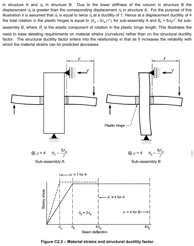
This picture from NZS3101 helps explain this concept, that the global ductility for determining the overall loads is independent of the local ductility demand occuring in members. You can for example design for mu=1 for determining the global base shear, but have certain elements that require ductile detailing due to the curvature they are seeing in potential plastic hinge regions.

Capture_xetoie.png

Capture1_vkaoni.png


The reason for the axial load limit is that walls traditionally don't perform that well under higher axial load because the confinement requirement isn't usually as rigourous as for columns.

In NZ for example we have an upper limit on N* of of 0.3 instead of 0.2f'cAg you note. But then traditionally we have always had quite strict confinement criteria when compared to most international standards. If we go over 0.2f'cAg then we need to also ensure the thickness of the wall doesn't make it too slender. Other than that we also have the provision that if you exceed this axial load limit you have the option of designing the wall following the column provisions (which in theory will result in higher levels of confinement).
 
That makes a lot of sense, however based on my design experience in Australia the global ductility class assumed for the building is used throughout in the design and detailing of the vertical lateral load resisting elements. I am not aware of breaking it up into global and local ductility, and the code certainly does not go into that sort of detail, perhaps due to being located in a region of low seismicity.

Rapt has also alluded to the fact that the "ductility assumptions for all structural walls need to be consistent across the structure..." Further, with reference to a recent paper concerning AS3600 and the design of reinforced concrete walls in regions of lower seismicity, it quotes that the "ductility class assumed for the building should be that of the least ductile element within the lateral load resisting system." Both these statements appear to attest to the fact that a single global ductility should be adopted, at least in regions of lower seismicity like Australia, but I may be missing something?

Notwithstanding the above however, and referring back to clause 14.4.4.3 re: axial load limits, there are no provisions on detailing if you exceed the 0.2f'c stress limit - its a dead end. So if you have assumed a limited or moderately ductile structure, and designed and detailed the main lateral load resisting elements (core and shear walls) to suit, but a handful of columns happen to exceed the 0.2f'c limit (which is highly likely in almost all scenarios as far as I'm concerned), it appears you will need to revert to a non-ductile system for all elements (not a great result), or increase the size or strength of the columns in question in order to maintain the limited or moderately ductile assumption made initially. I would expect (as you noted) that if you exceed this limit, it would simply tip you into more stringent detailing requirements, but there are currently no provisions like that in this regard.
 
Clause 14.4.4.3 states that the 0.2f'c limit applies to walls; it does not mention columns. I'm not sure if that means as long as you design the wall using Section 10 of the code you don't have to meet this requirement. I suspect that was not the intent of the authors of the code; however, it's certainly not clear.

There does not seem to be a clear definition of the difference between a wall and a column in the code other than 5.6.2.
 
Drapes,

The logic is meant to get you to increase the column dimensions until the clause is satisfied! It is an absolute maximum, independent of detailing.

Apparently it has been shown that having too high a pre-compression of a wall limits its ability to behave in-elastically and therefore perform its post-elastic plastic drift. A bit like the more stringent ductility limits for beams which have to have sufficient ductility to allow sufficient plastic rotation to occur after a plastic hinge forms.

As you should not be mixing ductility of elements (as you have discussed above) then you cannot simply say the offending wall is non-ductile if all others are limited ductile or moderately ductile.
 
Thanks rapt, that makes a lot more sense now.

Interesting then that if we choose to proceed based on limited or moderate ductility, that the sizing/strength of the heavily loaded columns (possibly the vast majority of cols on the lower floors) may now be dictated not by ultimate gravity load combinations but by the axial load limit under its seismic weight.

Retrograde, based on discussions herewith I believe "structural walls" under seismic loads relates to all vertical loadbearing elements whether they are walls or columns, that is any wall connected to the floor diaphragm that attracts horizontal earthquake or wind action (that includes columns as far as Im concerned). Remember, if we choose to proceed based on limited or moderate ductility, then we will need to design all walls as columns using section 10 anyway, as the simplified method will not be allowed in this instance as per cl 14.4.4.1.
 
Drapes

Probably not when you start looking at the numbers. Seismic weight is a lot lower than factored gravity load and gravity load combined with wind will have significant moments associated making the controlling stress under gravity load and possibly wind a lot higher than the seismic load stress which has no moment effects included.
 
rapt, agree however you can use the longitudinal reinforcement to your advantage under factored gravity load or gravity load combined with wind, but for the axial load limit check under seismic weight the reinforcement is disregarded
 
That makes a lot of sense, however based on my design experience in Australia the global ductility class assumed for the building is used throughout in the design and detailing of the vertical lateral load resisting elements.

Took us 35 years to sort it out (our code up unto 2006 used to be exactly the same), you'll get there eventually to.

But in the interim if that is true with the detailing required being tied to the global ductility then you're certainly doing it incorrectly. It has nothing to do with low seismicity.
 
Status
Not open for further replies.

Part and Inventory Search

Sponsor