Continue to Site

Eng-Tips is the largest engineering community on the Internet

Intelligent Work Forums for Engineering Professionals

  • Congratulations KootK on being selected by the Eng-Tips community for having the most helpful posts in the forums last week. Way to Go!

Structural Wall" definition AS3600-2018 3

Status
Not open for further replies.

QSIIN

Structural
Apr 21, 2013
50
Hi all,

Just want to get some opinions on the changes to "structural walls" in new 2018 AS3600.

Section 14.2.10 defines a structural Wall as:
"Wall (either load bearing or non-loadbearing) connected to floor diaphragms that attracts horizontal earthquake and wind design actions".

At what point is a wall considered to "attract" EQ and wind actions? If we're talking about "gravity only" walls in a structure that has a stiff core and other lateral resisting shear walls, these elements might attract just a fraction of lateral actions - but they still attract some as they are connected to the diaphragm, but can you argue they aren't part of the lateral system and therefore do not need to comply with section 14, save for drift consideration? Or does pretty much any vertical compression element that is not explicitly a "column" now count as a "structural Wall" and must comply with 14.4.4.3?

Subject to the above, if you have "gravity only" walls, to section 11 in lieu of columns, but a ductile core, is the whole structure ductile or non-ductile? Even if the walls aren't part of the primary lateral system?

Section 11.5.2(b) limitations for the simplified wall design:
"Not to be constructed on sites with soil classification of De or Ee, AND where subjected to earthquake design actions"

Are those two limits mutually exclusive? Can you have walls that are constructed on De soil but not subject to EQ? Is that even possible? Can you have walls on Ce soil classification that are subjected EQ actions?


I think both these points are too vague and not explicit enough in their intent, and will be exploited to get away with using simplified wall deisgn in excess and to continue ignoring seismic design.

I understand the code is not meant to be a detailed how-to guide and their must be engineering judgement, but from my experience unless the code says "can do A, cannot do B", option b will be a viable solution for some..


Replies continue below

Recommended for you

Unfortunately, I think there is too much pressure from contractors to have the lowest rebar rate.

The train of thought is that if companies follow the correct detailing rules, they'll not be competitive and lose the job because they're too heavy.

 
Well, imagine there's been a significant seismic event in Australia sometime in the future and for the sake of a lack of few additional stirrups you know you were required by the codes of the time, you now have to personally live with being responsible for the deaths of 100+ people in a structure you designed.

For some practicing engineers in NZ, this is there reality. Knowing their flouting of the rules directly contributed to the deaths of 100+ people.

I find the lack of accountability and some formal regime for the peer review of projects in Australia quite interesting, as surely once the shoes on the other foot and you as peer reviewer are being asked to put your signature on a design you didn't do but know it doesn't comply would raise some concerns for most engineers wouldn't it. I'd hazard in this situation given the risks most engineers wouldn't feel comfortable signing off the others design as a reviewer, yet as a designer you're quite comfortable flouting the rules in the first place.

In NZ unless you can demonstrate compliance with the standards in plsce during the peer review process, you'll struggle to do your 'own thing' that significantly departs from the code writers intent. You can do alternative things like following other international standards or guidance, but you'd generally only do this if your standard lacked guidance in that area or had recognised flaws or shortfalls, or didn't reflect current knowledge. Codes are a minimum standard to achieve a recognised level of life safety. While we argue about numbers, don't forget what we do is primarily about maintaining life safety in the unfortunate event we see an ULS event.

It seems like Australian concrete standard has made a large leap recently in keeping up with current international best practice, but its outpaced the current knowledge and comfort zone of the engineer's as they struggle to make sense of all this new (to them at least) seismic stuff. As rapts noted, any modern text book should be able to clue people up on the basics. All these rules have a basis in terms of ensuring buildings stand up to real world events.
 
Self-certification allows shonks to flourish. It isn't a good match to price competition.

OTOH, Engineers Australia has an oversubscribed webinar coming up so plenty want to learn.
 
Thanks Agent666, a great resource indeed.

I came across another paper (which I alluded to in an earlier post) which appears to be a precursor to the new earthquake provisions of the code and is titled "RC walls in Australia: seismic design and detailing to AS1170.4 and AS3600".

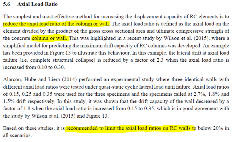
Rapt, with reference to this paper and going back again to the clause on the axial load limit for structural walls, recall you left off by assuming this limit probably did not apply to columns. Please see below excerpt from the above paper providing some commentary on this, where it initially suggests the axial load limit applies to BOTH walls and columns, however its concluding statement only references walls - I have highlighted these sections for clarity. What are your thoughts on this? Do you still believe this limit would only apply to walls given there will be a higher level of confinement provided by default in columns?

Capture_rmkvx7.png
 
Details of the paper quoted by Drapes:

To cite this article: Scott J. Menegon, John L. Wilson, Nelson T. K. Lam & Peter McBean (2018)
RC walls in Australia: seismic design and detailing to AS 1170.4 and AS 3600, Australian Journal of
Structural Engineering, 19:1, 67-84, DOI: 10.1080/13287982.2017.1410309

To link to this article:
The paper is available for free download to members of Engineers Australia.


Doug Jenkins
Interactive Design Services
 
Drapes,

I discussed this with the author of the paper mentioned above, Scott Menegon, before I gave that reply on Jan 24th.

If a column was the dominate stiffness in a sway frame and in single curvature, it may apply to it. If the column were a minor stiffness braced by more dominate walls and in double curvature, it probably does not apply to it.
 
"If the column were a minor stiffness braced by more dominate walls and in double curvature, it probably does not apply to it."

Does this mean then that there is a point where an elements stiffness can be deemed negligible and the tight EQ requirements wouldn't apply? This is essentially what I've been trying to get some clarity on.

If a long blade column is significantly less stiff than the core box, do the EQ requirements for structural walls still apply?

The EA presentation a few nights back, the presentor was asked about different Mu and Sp values for different elements in the same structure (short stocky walls in a high-rise). The presenter's response was that the ductility of a single element doesn't necessarily dictate the ductility of the whole structure, and different values could be adopted for different stages of analysis. This is kind of in conflict to the text under table 14.3
 
QSIN,

QSIN said:
If a long blade column is significantly less stiff than the core box, do the EQ requirements for structural walls still apply?

If designing in accordance with AS3600's and general Australian simplified earthquake design logic, the answer is still YES.

RE mu and Sp values,
The places where mu = 1 for a specific calculation are there for specific purposes.
e.g. A wall may be fully in compression under mu = 3, so a designer may think he can detail it as a compression only wall.
But under the extra plastic sway (drift difference between mu = 1 and 3), the wall then goes into tension, it must be detailed as a wall with tension. Otherwise, when it goes into tension,it is not designed/detailed to provide adequate ductility in that case.

So AS3600 tells you that the decision as to which design and detailing rules to use is based on Mu = 1, not mu = 3, (PS I have left Sp out of this but it varies as well) so that it is detailed for the failure condition not a simplified "elastic" (elastic in earthquake design terminology) strength condition.
 
QSIN,

Further to this, my earlier comment to Drapes only applied to the .2f'c limit in 14.4.4.3!
 
Thanks RAPT,

Cl 14.4.4.3 does state "All structural walls", and by definition (and what this thread is all about) shouldn't the 0.2f'c apply to all elements, regardless of their relative stiffness?

On another note, if the dominant element (say lift core) is in tension with a Mu of 2, it can be designed and detailed to Section 14, with enough tension steel required for the Mu=2 reduced tension force.

But if a wall is in tension with Mu=1 but in compression with Mu=2, what is the tension force to design for? Somewhere in the middle, or just the full Mu=1 tension force?
 
QSIIN, your last point is precisely what I am still a little confused about as well.

It appears the decision on whether a wall is in tension or compression, or whether the wall will require ligs, and other similar checks, needs to be based on the non ductile loads with mu=1 (full elastic earthquake load), irrespective of the system ductility assumed in the design even if its limited or moderately ductile with mu>1. The checks based on mu=1 will then inform the detailing requirements only (for example if you need vert bars on each face in lieu of central, or if ligs are required), however as far as the overall strength design is concerned this can still be based on the reduced loads with mu>1 provided the above detailing requirements have been met.

Im still unclear on the logic here though. Rapt and others may be able to confirm if this is the correct approach and shed a little more light on it.
 
I thought I answered your first question above. Yes, the code says all walls. Not columns. And yes there is a problem with this if engineers try to game the system by calling a wall a column based on some length to width ratio, which is why I tried (apparently unsuccessfully) to introduce some sensible relative stiffness logic into the discussion to explain why.

Mu = 1 controls the detailing requirements. Mu = 2 or 3 or whatever controls the moment and force to be designed for.

So Mu = 1 might tell you that detailing for a column in tension is required, controlling minimum reinforcement (e.g. clause 14.6.7, but not limited to this clause, there may be others) etc, but the compression and tension forces the column actually has to be designed for strength for are from mu = 2.

So mu = 2 might tell you that the column is fully in compression under the (elastic drift) which gives the design ultimate load. But mu = 1 says it is in tension under full plastic drift.
If the reinforcement was detailed based on mu = 2, then the amount of reinforcement supplied might not be sufficient to provide multiple cracks and ductile response under the full earthquake drift. Minimum for compression is .0025 or in a very lightly loaded column .0015.

Mu = 1 however tells you it must be detailed for tension as its extreme drift condition is tension, so the minimum reinforcement is the minimum required for tension to guarantee multiple cracking. This is controlled by 14.6.7 and is dependent on steel and concrete strength and is independent of the magnitude of the applied loads. In the plastic hinge zone, for 80Mpa concrete and 500MPa steel it would be .0125, so 5 times the compression minimum! This then reduces as you move up the building away from the plastic hinge zone.

So your starting point for the amount of reinforcement required is the minimum for tension in this case, not the minimum for compression (actually it is the higher of the 2). The column capacity is then checked for the mu = 2 applied moment and axial.
 
Hi again, just to keep this thread going...

CL14.4.4.3 Axial load limit for elements with u>1. The description says N*/Ag, where N* is the sum of the seismic weights defined in AS1170.4 (earthquake code). So, is this axial load limit only for G + 0.3Q?

It says increased axial load resulting from vertical ground accelerations, if appropriate, should be included, which would then only be applicable to Parts and Components in Section 8 of AS1170.4 - so maybe non-load bearing precast walls. EDC 1, 2 & 3 state vertical ground accelerations need not be considered.

But should axial load from horizontal load EQ be included in this? I would think so..

The paper by Scott Menegon and John Wilson, 'RC walls in Australia: design and detailing to AS1170.4 and AS3600, Table 3 states the 0.2 axial load limit for N* is calculated using the load combinations for EQ action in AS1170.0, which would be G + Eu + 0.3Q.
 
14.4.4.3 says Increased axial loads resulting from...system behaviour of the overall structure (eg frame action) should be included in N*.

I think this might be what you're looking for.
 
The loading is gravity load based on the seismic weight. The frame effects mentioned are frame effects on distribution of gravity load. This was mentioned to make sure that the effects or transfers and sway effects due to non-symmetrical structure and loading were included.

Horizontal earthquake load is NOT included.
 
Status
Not open for further replies.

Part and Inventory Search

Sponsor