Eng-Tips is the largest engineering community on the Internet

Intelligent Work Forums for Engineering Professionals

Strut & Tie - Offset Column design 2

Status
Not open for further replies.

KutEng

Structural
May 27, 2019
40
0
0
AU
I have been a long time lurker on eng-tips and have finally found the need to make a post for myself.

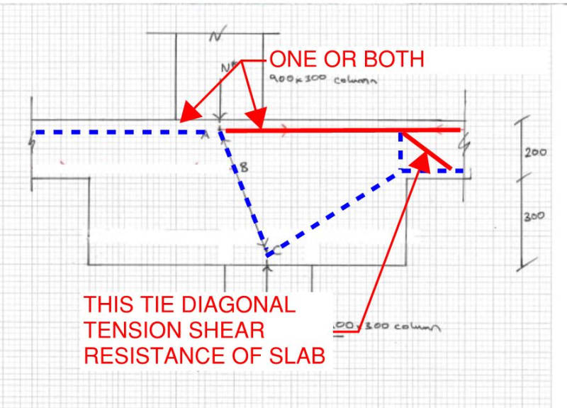
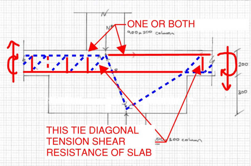
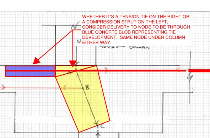
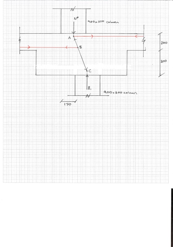
I have recently become familiar with Strut & Tie modeling and am currently faced with designing an offset column attached below. I have tried designing without a drop panel and my tie forces were far too high so added the drop panel in to increase the angle between the strut (black) and the ties (red). I know it would be ideal to have my bottom tie at node C however we do not detail reinforcement in the bottom of our drop panels at our firm.

I am wondering if my current model is reasonable (or even possible) with node B being midway through my strut. Am I missing additional struts or ties? Is this even a Strut & Tie problem or can I use standard methods of analysis? I am having trouble finding the resultant tie forces as I get different results when using the sum of all forces/moments or using simple trig so I'm assuming I am missing elements somewhere.

Any help would be greatly appreciated. Thanks.

STM_aaavph.jpg
 
Replies continue below

Recommended for you

This has a number of problems. Node C isn't in equilibrium. The strut AC would actually be two struts AB and BC. The force in the lower tie that connects to B must be zero because the AB and BC forces must be equal for vertical equilibrium so there is no unbalanced horizontal force.

But more fundamentally, you're trying to avoid reinforcement at the bottom of the drop panel. You can't say you'll design by S&T then exclude ties!

And are the columns in pure compression as you've drawn?
 
I would not use a strut-and-tie model unless I had to. The method can be very subjective depending on your assumptions. I stick with traditional methods whenever I can. Don’t over complicate things if you don’t have to.
 
Confirm for me that the horizontal compression strut would be much easier to just ignore from an analysis standpoint on the left side?

Also it appears (and maybe my analysis is a bit rusty) the lower column will see a slightly amplified force due to the restoring compression struct on the right side.

Edit: realized without diagonal tension resistance, you can't resolve the vertical compression.
Lastly, would it make more sense to take out the tension using the slab bottom bars as shown below in pink(assuming they exist through the drop panel), as opposed to relying on the tension shear resistance of the slab.

 
jayrod12 said:
Confirm for me that the horizontal compression strut would be much easier to just ignore from an analysis standpoint on the left side?

Confirmed. However, I prefer to show it as I do because:

1) My preferred approach here is to show as complete and accurate a picture of things as I can and then let OP pare it down to what she really needs. If the extra complexity results in extra confusion for the OP, I consider that a benefit. That confusion, in my mind, indicates an incomplete understanding of the situation a need to push a little further with respect to asking questions etc. To this end, I submit for consideration the even more complex, even more complete model below. I held back on this because the villagers tend to get antsy when they see ties crossing struts, partial depth model usage etc.

2) In many cases, where the joint is in the interior of a slab, the fact that the primary strut can push against adjacent, semi-infinite concrete is a) very comforting and b) can be used to advantage. As such, I feel that it's important to acknowledge the existence of that load path. Most of time, I suspect that it's actually this mechanism getting most of the job done. It's a rare building owner that would want to "see" their ties working when they look down at the top of a slab joint.

3) I think that it's key to a complete understanding of S&T to recognize that, wherever a tie bar is developed, there is a compression strut over lapping it that a) represents bar development and b) is not explicitly recognized in our S&T models. Whenever you think that you're pulling on a bar, you're also pushing on a cylinder of "development concrete" that surrounds that bar. For this reason, I feel that it's somewhat arbitrary, for a situation like this, as to whether or not one chooses the push or the pull as the designated path coming immediately out of the joint.

jayrod12 said:
Also it appears (and maybe my analysis is a bit rusty) the lower column will see a slightly amplified force due to the restoring compression struct on the right side

Agreed. I tend to think of the situation as analogous to a tip loaded cantilever with an indeterminate back-span. The support closest to the load will always see an amplified version of the load. It's a keen observation though. By the book, one should be carrying that amplified column load down through the rest of the building. And I suspect that rarely happens unless it's somewhat by accident via an all encompassing ETABS model etc.

c01_vgdfhc.jpg
 
KootK said:
The support closest to the load will always see an amplified version of the load. It's a keen observation though. By the book, one should be carrying that amplified column load down through the rest of the building. And I suspect that rarely happens unless it's somewhat by accident via an all encompassing ETABS model etc.

Normally with S&T, you know the boundary conditions at the B-regions from your analysis and set up the S&T model to suit, so this would be picked up if the stiffnesses made it happen. The model in this thread has been developed in reverse compared to what I'm used to.
 
Thank you all for the insight. I think I have enough now to get this going.

KootK, I understand the concept behind the development of the tie causing an overlapping strut, however, if I was to consider the horizontal strut at A along with the tie I would have 4 elements coming off node A. Is this consistent with STM theory or does it need to remain at 3 elements to a node for the sake of simplicity/calculation?
 
Ar_Engineer said:
KootK, I understand the concept behind the development of the tie causing an overlapping strut...

I suspect that there is still a degree of misunderstanding on this point given your question about the four elements coming into node A.

1) I know of no hard limit on the number of elements that can come into a node. That said, the impulse to steer things toward something simple is certainly valid.

2) Whether you use the horizontal tie, the horizontal strut, or both, I believe that the model is the same with only three elements coming in. See the sketch below. In my mind this is best envisioned as a CCC node at A for any condition where you're able to extend the tie bars left of the joint meaningfully. It's only a CCT node at A if you're geometrically constrained with an edge column condition etc. And if that's the case, many a designer would include a headed bar or a weld plate on the ties to, effectively, bring it back to a CCC condition.

c01_p1o7od.jpg
 
Trenno said:
I just want to know who in their right mind uses solid red lines for ties and dashed blue lines for struts...

- I dunno, I feel as though I have been in my "right mind" thus far.

- Is there some kind of ISO standard for this of which I'm unaware?

- Almost without exception, I see struts represented as dashed.

- With respect to what is hot colored and what is cool colored, I've seen plenty of both.

- Example below from a Concrete International / ACI.

c01_makkza.jpg
 
Tongue in cheek, KootK. Always thought of compression red being angry and sporadic (dashed) and tension blue being the calming influence of clearly defined (solid) rebar.

 
Noted. Your scheme does have appeal. I've always thought of red as representing "mission critical reinforcement". And blue as representing "relax KootK, the concrete will probably never ever crack anyhow".

 
You're most welcome Ar_Engineer, happy to help. Strut and tie's one of those things... seems dirt simple right up until you actually try to see a model through.

 
This one worries me. You can draw nice lines like that and tell the concrete where you think the forces will go. And yes, eventually the forces may go there. But the rotation is still going to happen. The slabs either side of the connection are not stiff enough to stop it and the forces in the struts still result in a high rotation.

As an very experienced engineer commented to me on this S/T arrangement,

"Most concrete structures did not go to uni to know how to behave...".
 
I agree rapt.

I always remember a lecturer in college shouting at one of my fellow students.. I don’t remember the context, but I always remember his words “...WELL THE CONCRETE DOESN’T KNOW HOW STRONG IT IS!!!”
 
I wouldn't treat a CCT node as a CCC node just because it's possible to anchor the reinforcement beyond the node. This is an implicit requirement of S&T design. CCT nodes have lower capacity because there is tension in one direction which 'activates' the tie. The opposite of the strength increase when concrete is confined with transverse compression.

And I agree with Rapt. If you're going to make up a load path in the S&T process (ie make up boundary stresses rather than take from earlier analysis), you should check what deformation is required to achieve those boundary stresses.

(That said, this small offset is about equal to construction tolerance in some worrying parts but they seem to get away with it. )
 
Status
Not open for further replies.
Back
Top