Continue to Site

Eng-Tips is the largest engineering community on the Internet

Intelligent Work Forums for Engineering Professionals

  • Congratulations KootK on being selected by the Eng-Tips community for having the most helpful posts in the forums last week. Way to Go!

Strut-Tie - Tie Development at Nodes (Starter Bars) 1

BacBac

Structural
Aug 11, 2024
19
Reviving this thread:

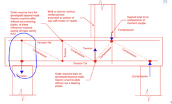
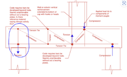
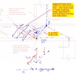
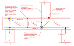
Does anyone have any ideas on how to justify the starter bars reinforcement is developed at the node?
For the shear ties, reference from Australian Standards, it's said to be fully anchored if shear ties detail is followed (AS3600-2018 clause 12.2.1 that refers back to Clause 8.3.2.4 for anchorage of shear ties).

However, nothing is referred for the development of the starter bars of the column.
Any help would be appreciated
Thanks!.
S&T Starter Bars.PNG
 
Replies continue below

Recommended for you

This is a problem I've come across in similar situations to your sketch.

AS3600 only requires that the tie extends beyond the node to achieve the design strength of the tie, not necessarily that it is fully developed beyond the node. It also says that you can get away with a minimum of 50% development beyond the node (i.e. a cog or hook), meaning you could place the node just in front of the cog/hook if these are present. The problem still is that, even with cogs/hooks, these would usually be placed above the bottom layer of reinforcement so the node would not really coincide with the bottom tension tie you have drawn. You might need to consider a separate load path from the base of the column bars to the other vertical bars in the pile cap/slab, which themselves can then be considered anchored at the bottom tie level.
 
One way to resolve this is to apply the tension from the column at a node close to the top surface, and the portion in the slab be handled by shear reinforcement. It's more like the shear reinforcement is lapping with the column starters in that solution though as they're in a straight line.

I would check how often a column actually ends up in net tension due to a moment, in my experience (at least in this region) it's pretty rare to not have enough vertical load to stay in net compression under combined axial + bending.
 
@bugbus:
AS3600 only requires that the tie extends beyond the node to achieve the design strength of the tie, not necessarily that it is fully developed beyond the node.
Agree with you. Does this mean that there'll be a case where you have more starter bars than your actual vertical reinforcement?
A coworker has suggested to always have double starter bars for this situation (assuming starter bars only developed by 50% at the nodes), but I don't think I have seen that kind of detail before.

It also says that you can get away with a minimum of 50% development beyond the node (i.e. a cog or hook), meaning you could place the node just in front of the cog/hook if these are present.
Are you saying that your interpretation of this sentence on the code is that if I have a cog or hook beyond the node, I can assume that bar is fully developed?


@Just Some Neds:
One way to resolve this is to apply the tension from the column at a node close to the top surface, and the portion in the slab be handled by shear reinforcement. It's more like the shear reinforcement is lapping with the column starters in that solution though as they're in a straight line.
The thing is, not all pile caps or transfer slab would have shear ties on it. Especially a thick pile cap supporting a core wall.
Do you typically put shear ties on the column strip of the said pile cap?
Moreover, for the case of a tension pile, I don't think we typically extend the shear ties into the top of the pile.
1731633649919.png

I would check how often a column actually ends up in net tension due to a moment, in my experience (at least in this region) it's pretty rare to not have enough vertical load to stay in net compression under combined axial + bending.
Agreed. This more of a case where lateral loads are applied to a cantilever column.
My actual issue is a case where a core wall/shear wall is supported on a pile cap.

Thanks all for the input.
 
Are you saying that your interpretation of this sentence on the code is that if I have a cog or hook beyond the node, I can assume that bar is fully developed?
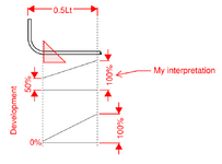
Not quite. I think you can assume the cog/hook provides an immediate 50% anchorage which might be enough capacity in some cases.

It depends on how the code is interpreted, whether the use of a cog/hook means the development goes from 0->100% from the end of the cog/hook to the point of 0.5Lt, or whether the cog/hook provides more of an immediate development of 50%. The code is not really clear, but my opinion is that the cog/hook provides the immediate 50% anchorage. I think that's the general consensus from what I've read on this forum before.

Screenshot 2024-11-15 134554.png
 
@bugbus
I agree the top one is the general consensus. The commentary of the AS3600 also makes it quite clear.

1731653242960.png

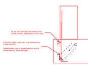
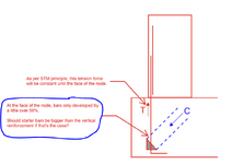
My issue with the starter bars is that since we only have cogs at the nodes ends, and the STM principle requires tension is constant at nodes face, should we put more starter bars than the column reinforcement bars?
Practically, I'd like to find the justification that the starter bars can just be the same size as the column reinforcement bars.

1731654114456.png
 
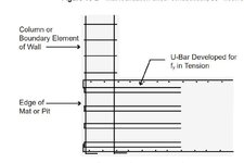
Why not make a whole loop instead of making an L shape (this would look like a vertical hairpin)? According to my understanding of Leonhardt's book "Vorlessungen uber massivbau" the whole loop (of course when both legs are in tension, he calls it "schlauf") develops almost instantly (I'm bad at german so I might be wrong) - if I remember correctly 3D from the end of the bend you get a bar fully developed.
I went through conclusions of a dissertation from 2022 I found about the anchorage of stirrups and these are their conclusions (based on experiments on 180° bends loaded in tension on both legs... straight portion was taped so it does not have bond with concrete, all anchorage was on the loop part):
- when cover (measured to the tested bar) was > 2.5D no side spalling was observed before yielding
- when mandrel diameter was > 10D no side spalling was observed before yielding
- even a small distance between multiple bends is sufficient to increase the spalling strength (distance between bends on the same bar, not two bars next to eachother)
- the casting direction had no influence on the spalling strength

There is also the new generation of Eurocodes which says something weird - 11.4.6 (1) For U-bar loops subject to pure tension, anchorage may be considered to be provided if the loop details comply with 11.3.
where 11.3. talks about permissible mandrel diameters and spacing of loops. The way I interpret this is "it is fully anchored at the end of the bend if the mandrel diameter is large enough", but maybe someone here has a better idea.
Moreover, for the case of a tension pile, I don't think we typically extend the shear ties into the top of the pile.
How do you transfer tension to the pile? You must have some reinforcement.
 
Last edited:
@hardbutmild
Thanks for the comments. AS3600 also states that if the diameter of the bend is >10db, then the development of the bars can be assumed to be continuous.
For low rise building, the thickness of the wall is typically 200mm, you barely can fit the U-Bars with 10db internal bend, which is why the typical detail usually has L-Bars as starter instead of U.

How do you transfer tension to the pile? You must have some reinforcement.
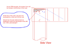
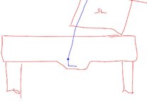
I believe it'd be through this STM mechanism here (1st screenshot). But typically, we stop the shear ties to the face of the pile (see 2nd snapshot).
But then again, similar to the starter bars, how do you justify that at the top node, the pile tension reinforcement is developed?

1st screenshot:
1731676730614.png

2nd screenshot:
1731677622348.png
 
AS3600 also states that if the diameter of the bend is >10db, then the development of the bars can be assumed to be continuous.
What does it mean that development can be assumed to be continuous?

I see, you do have reinforcement that goes from the pile to the top, that is good. I agree with your 2nd screenshot.
You can try making the mandrel diameter larger than in a standard hook. Eurocode 2 and fib model code 2020 adopted a formulation from here: https://www.sciencedirect.com/science/article/pii/S0141029621010506
There is an expression to get the stress at the end of the bend, it depends on the bend diameter... that way you can increase the bend diameter to resist the whole yield stress.

You could also add transverse bars inside the bend, that will also increase the allowable stress. For example, if you have a 90° bend and mandrel is 10*D - adding 2 transverse bars of the same D will give you a 40 % increase in the allowable stress (this is according to the new eurocode 2).
 
"What does it mean that development can be assumed to be continuous?"

It means you get no benefit from the bend. It is simply based on the length of the bar.

RE Development of the tension tie, I think you should read 7.3. You need to develop the strength at the node!
 
@hardbutmild
Thanks. I'll research more on increased bend diameter to allow for better anchorage.

@rapt
Thanks for explaining the 10db bent for me.

RE Development of the tension tie, I think you should read 7.3. You need to develop the strength at the node!

It's noted that we need to develop the strength at the node, but as per the original thread here (https://www.eng-tips.com/threads/strut-and-tie-tie-development-at-nodes.513462/), the original author is questioning the anchorage of the vertical ties in the STM model.

I found the justification for internal vertical ties (for shear) detail anchorage (AS3600-2018 clause 12.2.1), which then narrows the issue to:
1. Reinforcement anchorage at the base of the starter bars of wall/column with tension. (see screenshot on post #6)
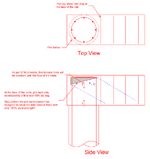
2. Anchorage of the tension pile's reinforcement at the top of the pile cap. (see screenshot on post #8)

With the STM, from my previous screenshots, it's shown that at the nodal zone, we're only able to develop a little over 50% (screenshot on post #6 and #8).
The typical detail/practice I've seen so far is to have the starter bars (L-bars) to match the size and spacing of the wall/column vertical bars and pile contractor designing their tension pile with 100% yield strength (typically 500MPa in Australia).
I was wondering if this is an oversight in the industry practice or if not, what's its justification.
As this is a typical case on all projects (core wall starter bars, tension piles), I don't want to start adding double starter bars or headed reinforcement for all my wall/column starter bars, or force the pile contractor to design their tension reinforcement with ~50% yield strength if there's a reason not to add these additional costs.
 
Stirrup bend details are a special case and the code assumes full development for this.

If the vertical Ties have a standard hook/cog, that is not equivalent to a stirrup detail and only provides 50% development according to AS3600.
 
@rapt
Thanks, rapt.
In short, are you saying the answer to these 2 questions is yes if we follow the standard hook/cog detail as per the typical industry practice?

1731807372320.png1731807412360.png
 
One way to resolve this is to apply the tension from the column at a node close to the top surface, and the portion in the slab be handled by shear reinforcement.

I think that's your story if there's shear reinforcement. If there's not shear reinforcement, then that same job gets done by concrete in tension, either by way of a diagonal shear plane check or an anchorage check.

c01.JPG
 
If it's a situation where you really gotta tell an STM story at the tension bars, then I think that's some kind of hardware or a local thickening. Neither is a recipe for broad spectrum popularity.

c01.JPG
 
@KootK
Thanks for the recommendation.
What do you mean by “really gotta tell an STM story”?

I’m just wondering to find a way to justify the current typical detail (where cogged/hooked starter bars match the size of wall vertical bars) actually works before I introduce unnecessary changes.
Especially, this will affect the detailing of the typical core wall to pile cap detail and how we instruct pile contractor to design their tension piles as explained in post #11.
 
What do you mean by “really gotta tell an STM story”?

I was referring to your regulatory environment and the standard of care where you practice. In my market, I would consider myself to be at liberty to justify the standard starter bar arrangement by way of methods other than STM, and sometimes not at all. But codes are getting more stringent around the world and it may be the case where you have no choice but to tell a strut and tie story in order to remain kosher.

Nobody in my market, including me, would sweat the typical starter bar arrangement for a column so long as:

1) No net uplift,

2) Not an edge condition.

3) The starter bars get developed.

4) Probably some other stuff I've not thought of.

And, frankly, most non-me engineers in my area wouldn't even sweat that stuff.

The tension zone reinforcing of a hard working shear wall is starting to get into the territory where STM might be appropriate in my opinion, particularly with an edge condition. You are starting to see more attention get paid to this kind of stuff in the literature, albeit not quite STM yet: https://www.nehrp.gov/pdf/nistgcr12-917-22.pdf

Presently, a world in which a thing can only be justified if it can be justified via STM is not palatable to me. Perhaps chatGPT will be more up to the task of that.

c01.JPG
 
@KootK
Thanks for your insight.
Unfortunately, my new manager insisted to have larger starter bars on all starter bars where there's tension due to bending unless I find a justification not to.
Seems like his previous firm always put larger starter bars under core, but I just haven't seen other firms (including my current firm) do it.
 
Unfortunately, my new manager insisted to have larger starter bars on all starter bars where there's tension due to bending unless I find a justification not to.
Ba! That isn't just incorrect, its bass-ackwards. Smaller bars always perform better than larger bars.

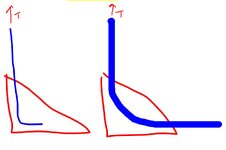
Activating a strut and tie mechanism in the real world involves a significant amount of cracking and redistribution. Obviously, in such a situation, it behooves one to have tie reinforcement that is fully developed within the nodes for fy wherever possible. The last thing that I want in a real world STM is some giganormous bar that is just barely hanging on to its node by the hook extension.

Tell your new manager to get an ET account and get in the ring.
 
For the same force and node geometry, does anyone really feel that the condition on the right is the better of the two?

c01.JPG
 

Part and Inventory Search

Sponsor