Eng-Tips is the largest engineering community on the Internet

Intelligent Work Forums for Engineering Professionals

Tangent edge transition standard

Status
Not open for further replies.

Stick369

Mechanical
Apr 9, 2010
17
0
0
US
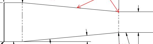
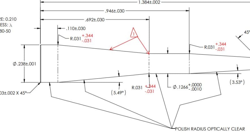
We have a part with a cylinders that transitions to a larger diameter with a tapper at both ends of the tapper there is a transitional radius/fillet. See attached image_1
Image_1_knflpo.jpg


The vender recently devlivered a batch of parts with an "undercut near the smaller diameter. See attached image_2
image_2_acvlln.jpg


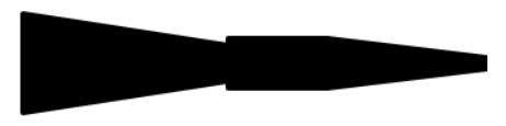
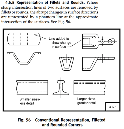
Their position is that because the drawing doesn't say they can't put in an the "undercut", its allowed. Insert mental image of lots of dumb looks. I'm having an issue finding which standard covers the intent, or purpose, of a tangent lines representation. Something that says a tangent edge represents the transition between two continuous surfaces. Or something that say unless the geometry is on the print, its not supposed to be there.
 
Replies continue below

Recommended for you

Hi, Nhaner:

I tend to agree with your vendor. If you have a special requirement, you'll need to call it out. If you don't, then the part meets your specifications.

Best regards,

Alex
 
Thank you for the laugh. Sourcing a new vendor has been recommend.

As far as standards go ASME Y14.5-2018
4.5.2.1 states "Where location of the center is unimportant, the drawing shall clearly show that the arc location is controlled by other dimensioned features such as tangent surfaces"
4.5.5 states "Where corners are rounded, dimensions define the edges, and the arcs are tangent"
4.16.1 state "When the center of the radius is not located (tangent located), the arcs are tangent to the adjacent surfaces"

Websters defines tangent as "a line that is tangent - specifically : a straight line that is the limiting position of a secant of a curve through a fixed point and a variable point on the curve as the variable point approaches the fixed point"

My only hope is that this is a big enough stick to hit them with.
 
@jassco - the special requirement has been specified with the use of a tangent arc between two surfaces and diameter dimensions. I've attached a more complete image of the dimensioned view
Image_3_bz3dqv.jpg
 
Standard mentions sharp edges being rounded, there's nothing in it about adding undercuts:

Untitled_fjhqp3.png


jasso, are you the vendor?

"For every expert there is an equal and opposite expert"
Arthur C. Clarke Profiles of the future
 
No, I'm not the vendor. I'm the Drafting Supervisor, and I'm responsible for documentation control and configuration management at our business unit.

The absence of data does not mean you get to add your own. The section and image you provided does not state you are allowed to add an additional feature. It clearly states that the intersection of two surfaces are done with a fillet/radius, the change in surface is repented by a phantom line (transitional change between two surface). If the undercut was part of the geometry it would be an object line representing a hard edge or an "abrupt change in surface"
 
Nhaner, I was wondering if jasso was the vendor, you didn't have to take it personally :)

The standard was ASME Y14.3-2003 MULTIVIEW AND SECTIONAL VIEW DRAWINGS.

You may need more than Y14.5 in your uphill battle with vendors. This comes to mind:

Untitled_qqa0wp.png


Good luck!

"For every expert there is an equal and opposite expert"
Arthur C. Clarke Profiles of the future
 
Sorry about that, thought it was a question from jasso. This is my first thread on eng-tips. I've used the knowledge found here in past discussion and was my first thought as a place to ask for help.
 
Hi,Nhaner:

"specified with the use of a tangent arc" is not specification. A specification needs to have an USL (Upper Specification limit) and an LSL (lower Specification Limit). In another word, how tangent they need to be. If you want to reject the parts, you have to inspect all those dimensions. You can reject them if the parts don't meet R.031 assuming that you have a tolerance for this dimension.

No. I am not the vendor.

Best regards,

Alex
 
The tangency between the two surfaces is completely removed if an under cut is added. Which means the two surfaces that should be tangent to each other at any limit are no longer tangent and the part is not made to print.
 
There is always the potential for mismatch because, sad to say, "tangent" isn't tangent at sufficient magnification - typically no one cares because vendors use the unwritten rules about not making noticeable sharp changes in part contour.

There is no tangent variation control in Y14.5; typically it would fall under surface finish limits where the step is larger than the allowable roughness.
 
ASME Y14.5-2018 4.16.1 states "When the center of the radius is not located (tangent located), [highlight #FCE94F]the arcs are tangent to the adjacent surfaces[/highlight]" Between that and our 63rms on the print, sounds like the tangent is controlled.
 
That is not a control - a control has limits. There are no variation limits and therefore it is not a variation control.

If you magnify the part you will see the cutter marks, possibly little cusps in the thousands - each one non-tangent. Grab an electron microscope if needed.
 
Hi, Nhaner:

"Tangency" is not a specs. To qualify this feature as a specs, you need to define its limits. Tangency in your case is a design intent. There is nothing on your print that states how tangent the transitions need to be.

There is no such a thing called "Tangency" in real world. It is imaginary in Math. If you examine your parts under a magnify glass or microscope, you will see ton of imperfections. If you have this concern with your parts, then you need to call out surface finish as 3DDave suggested.

Best regards,

Alex
 
There is nothing unequivocal against it in the Y14.5 standard. To avoid the issue, a profile of a surface control on the conical section could be defined. It's clear that the included angle is not as designed.
 
Hi,Nhaner:

There are three levels of control on part geometries per ASME B46.1 standard. They are as follows:

1. Profile control;
2. Waviness control;
3. Surface finish control.

You can use them according to your needs. Profile control of the conic geometry seems appropriate as Burunduk suggested. If you want to do nick-picking (LOL), you may need to tap into waviness and surface finish controls. But they are at different level of controls.

Good luck!

Alex
 
Status
Not open for further replies.
Back
Top