Continue to Site

Eng-Tips is the largest engineering community on the Internet

Intelligent Work Forums for Engineering Professionals

  • Congratulations SSS148 on being selected by the Eng-Tips community for having the most helpful posts in the forums last week. Way to Go!

Theoretical fork supports vs Simple connections in practice

Status
Not open for further replies.

Eagleee

Structural
Feb 14, 2017
51
Hi everyone,

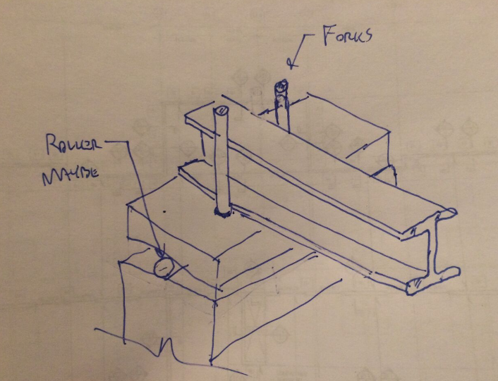
Being a relatively new structural engineer, I am trying to get a feel of when differences between theory and practice are ignored / deemed as unimportant by structural engineers. Although I have an idea about the answer, I wanted to ask you about an aspect related to lateral torsional buckling. Most elastic critical moment formulas assume the ideal fork supports at the ends of a beam. In reality, connections neither fully restrain or allow a certain motion, but somewhere in between. I guess the same applies to torsion at the end of a beam. I have seen that differences in critical moment between when a beam is restrained from rotating about its longitudinal axis at one or both ends and when it is free to twist are quite large. This of course is intuitive. Since designers often go for simplicity where possible, I have seen many instances of common, simple beam to beam connections that do not seem to offer a proper torsional end restraint for the supported beam. Do you ever check or think about this aspect when designing?
 
Replies continue below

Recommended for you

Eagleee - Are you asking about designing an end connection for torsion due to a torque being placed on the beam, or are you talking about resisting end rotation for stability at a simple connection? If it is the latter, it is super easier to design a simple connection to prevent excessive out of plane rotation for reaction stability. Clip angles or single shear plates should be nearly full-depth, i.e. between web to flange fillets in an I-section. Other simple connection configurations have different ways to handle that stability.

When modeling in many 3D analysis programs, ends of beams in many models may need to be torsionally restrained to maintain global or local stability of the frame. Of course, this fixity can attract torsional moment in the beam. How much depends on the configuration of the frame, loads, and the torsional rigidity of those members. Often times you will find that when you check the analysis output, the tabulated torsional moments are very small or near zero. It is up to the engineer to decide when those torsional moments are appreciable enough to warrant an actual moment connection. Usually, the most cost-effective way is to use kickers, etc. to make the torsion in the beam go away so no moment connection is required or to prevent beefing up the beam section. Spandrel/fascia beams are a typical example when you have hanging facade from the beam. Without kickers, or some sort of horizontal member lower to the beam, the torsional moments would lead to uneconomical sections.

The AISC Steel Manual has examples and commentary regarding simple beam and torsional stability. Not near mine, or else I would point out the sections. The only other thing I was thinking (but don't know the answer) is whether the design codes have empirical components within the LTB equations in order to account for some reasonable minimal support restraint. The code specifically requires this stability detailing at every beam support no matter what. However, I know for a fact that many engineers design loose laid W-sections bearing on masonry and concrete without proper support torsional restraint. I see home builders making the same mistake regularly.

One in the hand is worth two in the bush.
 
MacGruber22, thanks for the reply. I am asking indeed about the second case, so no external torsion present on the beam. Therefore, unless the beam is modeled with a LTB eigenmode type imperfection (which I am quite sure is done extremely rarely in practice and only studied in more detail in academic cases), no torsion would be present at the connection. However, all analytical formulas assume fork end supports for the calculation of the elastic critical moment of the beam, as far as I know (this is related to the empirical components you mention within LTB equations ). So theoretically, it seems to me that the use of any of these formulas would directly imply that torsion is restrained at the ends of a beam. I have tried to quantify for instance the difference (using the free software LTBeam) between a beam torsionally restrained at both ends vs torsionally restrained only at one end and the difference in elastic critical moments for both cases can easily result in different minimum required sections. This got me wondering if designers 'link' this aspect of member design to the connection design.

I am using Eurocodes and to my knowledge this issue is not touched upon. I will have a look through the AISC Steel Manual.

MacGrubber22 said:
However, I know for a fact that many engineers design loose laid W-sections bearing on masonry and concrete without proper support torsional restraint. I see home builders making the same mistake regularly

This touches on the matter perfectly. Both from the fact that the stability of the beam is not properly ensured and from the fact that the W-sections may have a lower LTB capacity than assumed in the design. That is how I see it at least.
 
I would say that engineers almost always give some thought to providing rotational restraint at beam supports but almost never quantify the extent of that restraint with calculations. It doesn't take much usually. Some conditions with cantilevers and temporary/lifting beams can be more critical. I can't remember where but I've seen some literature indicating that even loose beams with stiffeners often have adequate restraint.

I like to debate structural engineering theory -- a lot. If I challenge you on something, know that I'm doing so because I respect your opinion enough to either change it or adopt it.
 
I agree with KootK. Usually by "feel". I guess stiffened web only bearing connections would be OK if flange width is healthy compared to depth. I would envision the stability of this connection to be resolved by a combination of bearing friction and rigid body rotation resistance (slip and tip). Still don't like it though.

Eagleee - For kicks and giggles, calculate the approximate required bracing force at mid-span of a w-shape (0.02*M/0.85d). I *think* 0.85 is the correct estimated average ratio to get to the lever arm between the flanges - if not, close enough. 2% is an average bracing force requirement that I was taught (with healthy skepticism). That brace force is usually surprisingly small when you consider the typical simple span framing connections used (practicing engineers and fabricators always have minimum plate thickness, rows of bolts, etc). The skinny of it is that simple connections generally have a decent amount of reserve. As I am sure you are aware, the other bracing requirement is stiffness, which is a bit more of a challenge to think about when trying to determine exactly what torsional rotational stiffness at the simple connection is required to be valid under whatever LTB model is being used.

One conventional simple framed connection that could give me pause in the right situation is the so-called AISC "extended configuration" of single shear plates. Torsional stiffness is much lower in this kind of connection than the other typical ones because the plate is cantilevering appreciably from the support. Of course, if you can get a lateral framing member close to the connection, that can be mitigated.

I guess the summary is to follow the building code, fill in the gaps with engineering judgement, and rarely calculate directly.

One in the hand is worth two in the bush.
 
OP said:
I have tried to quantify for instance the difference (using the free software LTBeam) between a beam torsionally restrained at both ends vs torsionally restrained only at one end and the difference in elastic critical moments for both cases can easily result in different minimum required sections.

I don't doubt it, especially for wide flange. Your Lb would be more than twice the value for restraint at both ends because you'd lose the ability to engage the section warping resistance altogether.

The common case of propped cantilevers without tip restraint is especially interesting in my opinion. You typically handle it by using the same elastic critical buckling moment that you use for simple beams but with a modified effective length factor. But then that Mcr equation assumes a certain degree of warping restraint that will depend on the back span for a cantilevered beam. But then we don't seem to actually account for the back span length in our LTB calculations for cantilevers. Messy.

Macgruber said:
I would envision the stability of this connection to be resolved by a combination of bearing friction and rigid body rotation resistance (slip and tip). Still don't like it though.

I see it the same. I like to think of these things in terms of energy and how buckling can be thought of as reorganization to a lower energy state which, in this context, usually means the load moving closer to the ground. In many of these sketchy scenarios, the load would actually have to move further from the ground temporarily before initiating rollover. That doesn't necessarily make these beams safe but it helps to explain why we don't see more problems than we do.

I like to debate structural engineering theory -- a lot. If I challenge you on something, know that I'm doing so because I respect your opinion enough to either change it or adopt it.
 
MacGrubber22 said:
One conventional simple framed connection that could give me pause in the right situation is the so-called AISC "extended configuration" of single shear plates. Torsional stiffness is much lower in this kind of connection than the other typical ones because the plate is cantilevering appreciably from the support

This is indeed one of the types of connections I was thinking about. Notched connections with shallow end plates as well maybe?

MacGrubber22 said:
That brace force is usually surprisingly small when you consider the typical simple span framing connections used (practicing engineers and fabricators always have minimum plate thickness, rows of bolts, etc)

I have noticed the low magnitude of brace forces. To make a small analogy to the column buckling case, I also believe that at least theoretically brace forces decrease as stiffness of the brace is increased, at least after a certain point. Feel free to immediately correct me on this due to obvious reasons, but I think that once the brace is stiff enough to force the member to buckle in a 'higher' mode, its received load will decrease.

MacGrubber22 said:
I guess the summary is to follow the building code, fill in the gaps with engineering judgement, and rarely calculate directly.

The problem appears when, at least in the Eurocode, apart from the calculation of the member after determining its LTB slenderness, no real specifications are given. Hence, I wanted to appeal to the engineering judgement of more experienced folk.

And KootK I have to say that your last paragraph, which resembles some of your other posts on this forum, offers a beautiful way of thinking about these issues. It seems like what a Feynman structural engineer would say, no doubt about it.
 
What, pray tell,is a ”Theoretical fork support?”
 
A bearing support that comes with a small diameter post either side of the beam that restrains rotation but otherwise does not affect the beam. It's a hypothetical construct used to investigate lateral torsional buckling laterally.

I like to debate structural engineering theory -- a lot. If I challenge you on something, know that I'm doing so because I respect your opinion enough to either change it or adopt it.
 
Koot:
Thanks much. I assume the two small dia. posts come into the beam or beam support horizontally from each side and are fairly strong in compression but very soft in flexural strength, to prevent only beam rolling or rotation. Correct? I’m going to have to invest in a few new engineering textbooks if I want to keep participating here on E-Tips. More and more I don’t understand the newest clever terminology, although the concept didn’t come along just yesterday.
 
Eaglee said:
It seems like what a Feynman structural engineer would say, no doubt about it.

Thanks for the kind words Eaglee. Coincidentally, I read Feynman's six not so easy pieces a couple of months back. Trying to stay ahead of a kid making his way through the highschool science curriculum. The man did have a gift for elucidation.

Eaglee said:
Notched connections with shallow end plates as well maybe?

This has gnawed at me in the past too. In essence, it reminds me of open webbed steel joists which are generally braced close to the ends for just this reason. See tension chord buckling: Link. In some form, the same thing's gotta apply to all flexural members. If you've got the stomach for a lengthy read, we did some excellent and comprehensive work on lateral torsional buckling here: Thread

Eaglee said:
I also believe that at least theoretically brace forces decrease as stiffness of the brace is increased, at least after a certain point.

I agree. The force in the brace is really a function of the magnitude of imperfection and movement in the point being braced. And since a more flexible brace yields more brace point movement, you have to deal with a greater force.


I like to debate structural engineering theory -- a lot. If I challenge you on something, know that I'm doing so because I respect your opinion enough to either change it or adopt it.
 
dhengr said:
More and more I don’t understand the newest clever terminology, although the concept didn’t come along just yesterday.

Frankly, I'd never heard the term before either. The pic below just popped into my head when I read it. Hopefully I've represented Eaglee's concept faithfully.

Capture_mtzqno.png


I like to debate structural engineering theory -- a lot. If I challenge you on something, know that I'm doing so because I respect your opinion enough to either change it or adopt it.
 
KootK, I know that LTB thread very well, I created an account for this forum soon after reading it. If the problems we are facing nowadays would be discussed in a similar manner, the future would look oh so bright. And you are of course right on the money with the pic.
 
One thing is for sure, since that thread, I am cautious to rely on only metal deck (or something similar) at a top flange to do all of the LTB resisting. LTB is a function of torsional stiffness and not using a couple to resist LTB when torsional stiffness is low makes no sense to me. Need a couple to resist a couple.

One in the hand is worth two in the bush.
 
Status
Not open for further replies.

Part and Inventory Search

Sponsor