Eng-Tips is the largest engineering community on the Internet

Intelligent Work Forums for Engineering Professionals

Thermodynamic cycle that can reuse latent heat of condensation 8

Status
Not open for further replies.

haruosan

Computer
Jun 27, 2023
41
0
0
US
I'm developing a thermodynamic cycle that transfers existing heat to generate steam. The heat transfer includes reusing the latent heat of condensation harvested at the condenser to heat the working fluid. Normally, this is not possible because the condenser is not the hottest point in the cycle and therefore any heat harvested cannot be transferred back into the working fluid which is hotter at any point in the cycle before the condenser. This limitation does not exist in the cycle I'm developing. Unlike a Rankine Cycle which generates high temperature heat for the generation of superheated steam, this cycle uses and re uses low temperature heat for the production of steam.

I'm looking for a mechanical engineer who'd like to be a cofounder for a green tech company based on this cycle. Preferably you live in CA or would be willing to move to CA at some point after funding is achieved and you are receiving a salary. The skills needed to prove the viability of the cycle and develop it are:

CFD
Heat Balance
MATLAB
Simulink
CAD
Turbomachinery
Electrical Engineering knowledge is a plus

I am familiar with OpenFOAM, Fusion360, MATLAB and other tools.

Please respond only if you are interested, have the skills, and are willing to become a cofounder.
 
Replies continue below

Recommended for you

Flash vaporization transforms the sensible heat already contained in the water and directs it to latent heat of evaporation. There's roughly 60% of the latent heat of vaporization contained in water at 373K. When this heat is used for phase change the resulting vapor is cold. This cold vapor is a heat sink for the condenser. The cold vapor, of course, will need to be heated before it enters the condenser and it is the latent heat of condensation that accomplishes this heating. Vapor, or steam, has the lowest specific heat of water at 1,996 J/kg/K to increase by 1 degree.
 
This query seems to be somewhat different from the one you posted a few months ago. Sees a bit ambiguous without a PFD. There was no PFD in your previous posting either.
If you are recovering heat of condensation from the working fluid in order to generate steam at low temp, then the condensor must be operating at somewhat in excess of 100degC, perhaps 150degC or so if you want LP steam at 50psig or so. What is this working fluid you have in mind, and is this cycle any more attractive than a regular organic Rankine cycle? Compression energy in your cycle must be way higher than a that in a regular ORC ( since you are running at higher temperatures), so show us that this cycle is better for each kW of compression expended.
 
haruosan said:
green tech
haruosan said:
this limitation does not exist in the cycle I'm developing
haruosan said:
low temperature heat

No disrespect intended but you are coming off very 'perpetual motion machine salesman' here. Getting a competent engineer to join your team may be difficult if you cant concisely explain the process. You are flashing water into cold vapor? Why?

Start with the basics: What is the working fluid and what are your hot and cold reservoir temperatures?
 
No disrespect taken. I do understand this sounds a bit like a perpetual motion device, but all thermal inputs are accounted for. The cycle doesn't flow because of some mysterious power or anything like that.

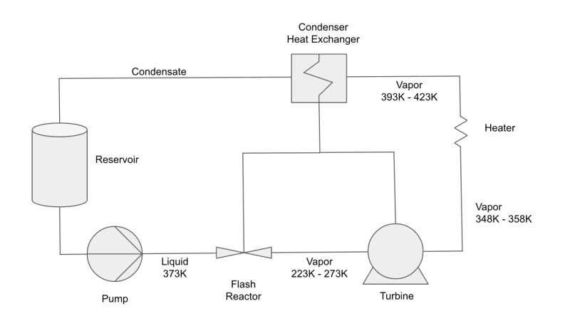
Here is a simple process flow diagram

Screenshot_2023-11-03_at_12.53.06_PM_jcigtz.png


*The working fluid begins the cycle in the water reservoir at 373K.
*Flash vaporization (Flash Reactor) transfers the sensible heat of the water into latent heat of vaporization - 1,323 kJ/kg
*The remaining 932 kJ/kg is added at the Flash Reactor and provided by latent heat of condensation - 932 kJ/kg
*Additional thermal energy provided by latent heat of condensation is added at the Flash Reactor to increase temp of resulting vapor to 223K - 273K - 445 kJ/kg
*Vapor enters turbine and is further heated to 348K - 358K by the latent heat of condensation as it flows through the turbine - 249 kJ/kg
*The vapor is further heated to 393K - 423K by an external source - 149 kJ/kg

After the initial cycle when latent heat of condensation is available, the total heat input is 149kJ/kg
The pump requires approximately 200kw of electricity and the external heat source 150kw.
 
TiCl4,

The condenser harvests the heat of condensation and transfers it to the Flash Reactor and the turbine. The vapor (working fluid) is the coolant for the condenser. The mass flow isn't stated, but let's say it's 1 liter per second. 3.6 tonnes of steam in an hour. The heat inputs listed are in kJ/kg so it can be easily extrapolated for higher flow rates.
 
You sound like a snake oil salesman. You can't just "harvest" energy like it is a piece of fruit. You can only transfer it from one mass to another. You have a mass stream going from the condenser Hx to the flash reactor/turbine. What is the source of that mass flow, and where does the mass go? From your sketch, it is simply injected into both places.

Perhaps if you had an actual drawing that accounted for both mass and energy flows, you may seem more believable. As it stands, this just sounds like yet another scam.
 
1) Your explanation doesn't make sense to me
2) Why work in K and not C? - your vapour appears to be < 0C so it freezes?
3) what extra useful energy do you think you're making here?
4) You have three lines going into your turbine - what are they doing?

Looks very odd to me....

Remember - More details = better answers
Also: If you get a response it's polite to respond to it.
 
Good luck with that; you'd be the first person in the universe to succeed with that.

Thermal energy is not "high quality" energy; it's all about temperature differences, but the initial temperature difference from boiling a fluid is something like 10x; which is not recoverable. You could possibly boil something with a much lower boiling point, like alcohol, but you'll never be able to boil water with recovered heat.

TTFN (ta ta for now)
I can do absolutely anything. I'm an expert! faq731-376 forum1529 Entire Forum list
 
TiCl4,

The condenser is up to 4,0000m^2 and transfers heat at 500 - 1000W/mK. The lines in the diagram show heat being transferred from the condenser to the flash reactor and the turbine. There is mass flowing along those lines, but within the condenser it is a closed system - essentially a thermal (phase change) heat pipe which collects heat from the large surface area where the steam condenses and drops it off at the flash reactor and the turbine.

What would be a good way to show just the heat transfer? Should those lines be red or dotted?

You can read about thermal heat pipe use for steam condensation in several studies:


LittleInch,

My apologies for working in K instead of C. I picked up the habit when calculating the amount of sensible heat contained within the water since the heat traverses a phase change at 273K (0C). Even from 273K to 0K there is thermal energy and it is accounted for in a flash process. Of course, the exit temperature of the vapor can be controlled by the amount of heat applied at the flash reactor. Add thermal energy and the vapor will exit at a higher temperature. Water vapor can exist as vapor below 0C. The vapors should exit the flash reactor below 100C so it can act as a coolant for the condenser. The larger the temperature difference, the more efficient is the heat transfer.

Most of the power of superheated steam is found in the phase change itself. Efficiency is gained by superheating, but it accounts for a small percentage increase over saturated steam. So, yes, because the vapor exits cold in this cycle, it does not have as much power as superheated steam, but still contains up to 70% - 80% of the enthalpy. And, it allowing the vapor to exit at a lower temperature, it can act as a heat sink to the condenser which allows latent heat re-use. Also, the cold vapor can be heated within the turbine to increase its volume and add work and torque to the turbine.
 
IRstuff,

Thank you for your response. The idea isn't to boil water (at atmospheric pressure), but instead to aggressively drop the vapor pressure of the water so a lower temperature can achieve the phase change - the same amount of thermal energy, but lower temperature. Even at low superheat (this is a flash vapor term not a superheated steam term) a flash process creates a usable shockwave.


Entropy is created when water phase changes into steam. When steam condenses, entropy is destroyed. Normally, the heat from condensation is lost to the cooling fluid and thus the environment. However, if your cooling fluid is the working fluid, then the heat is reused, not lost to the environment.

Think of this as a type of heat pump that uses pressure to move more heat than the energy input. A heat pump can have a COP higher than 1. Some commercial heat pumps can have a cop as high as 5 under the right conditions. This cycle is similar, but instead of just moving heat, it moves water through phase change, the kinetic energy of which can be utilized.
 
So you have a 100% recycle loop with steam between the condenser and the flash reactor/turbine:

1. How are you "depositing" energy into those units? Is this a steam powered turbine to pull vacuum on the flash "reactor"? Again, heat isn't something you can just "deposit" somewhere - you have to put the steam to work (steam-powered turbine) or transfer it with a large surface area.

2. After your flash reactor you have vapor less than 100 C. I assume, then, the purpose of the turbine i is to pull vacuum to enable low temp flashing? Or is this turbine producing electricity and I'm not understanding your sketch at all? You cannot produce vaporized water at less than 100 C without pulling a vacuum. If the turbine is generating power, how are you pulling a vacuum?

3. What is the theoretical efficiency of this theoretical cycle compared to a modern power plant?

4. Given you are operating with extremely low temperature differentials between parts of your process, you will require huge surface areas when compared with cycles operating at higher differential temperatures. Have you even thought about the CapEx part of the design?
 
TiCl4,

Thank you, again, for your responses. I copied and pasted your response below and added my comments:

So you have a 100% recycle loop with steam between the condenser and the flash reactor/turbine:

Yes.

1. How are you "depositing" energy into those units? Is this a steam powered turbine to pull vacuum on the flash "reactor"? Again, heat isn't something you can just "deposit" somewhere - you have to put the steam to work (steam-powered turbine) or transfer it with a large surface area.

The low pressure is created in the cavitation / flash reactor. The reactor is a specially designed Venturi valve that accelerates the velocity of the water and because of conservation of energy, the pressure at the inlet and throat of the reactor can be 0 Pa and even negative. This cycle does not rely on negative fluid pressure to work, but I add it here as a side note that negative pressure could actually help the phase change process. Many believe negative pressures do not exist, but they do in fluids. One of the reasons that negative pressure exists is because there is still hydrogen bond force at 0 Pa and all heat has already been used. If there is still an atomic force, there must be some other force to counter act it. Many studies show that water will resist cavitation to as high as -20 Megapascals. The remaining latent heat of vaporization after the 1,323 kJ/kg of sensible heat has been used is 932 kJ/kg, but there is no other heat available. The only remaining force is pressure. Negative pressure is achieved in the xylem of trees and Nasa has completed many studies of the topic of negative pressures in fluids and how it behave much like negative temperature. However, I state again, I am not relying on negative pressure for this to work. The pressure only needs to reach as close to 0 Pa as possible. Several papers describe that if you have a difference of 160 kPa between the inlet and outlet of a Venturi cavitation device, you can achieve 0 Pa pressure in the Vena Contracta and throat of the Venturi. This low pressure and heat transfer through the specially designed throat allows for enough heat to create saturated steam / vapor.

Supercavitation

Venturi Cavitation

2. After your flash reactor you have vapor less than 100 C. I assume, then, the purpose of the turbine i is to pull vacuum to enable low temp flashing? Or is this turbine producing electricity and I'm not understanding your sketch at all? You cannot produce vaporized water at less than 100 C without pulling a vacuum. If the turbine is generating power, how are you pulling a vacuum?

The Flash Reactor provides the low pressure for phase change. The turbine will be a turbomachine for a generator, but I am presenting this cycle without a generator for now to show how the heat balance works. However, the condenser and the turbine will achieve a level of low pressure to help pull the vapor through the turbine. The turbine has a vary large surface area for heat transfer. Again, the heat is supplied by the condenser (of course, after the vapor is heated by an outside source before reaching the condenser). Also, as the vapor expands in the turbine as it is being heated, the turbine will spin faster and create a slight negative pressure at the inlet of the turbine and egress of the flash reactor.

3. What is the theoretical efficiency of this theoretical cycle compared to a modern power plant?

I'd like for you to first understand the heat balance of the cycle. Do the heat inputs show that it's possible to transform the flow of water into vapor?

4. Given you are operating with extremely low temperature differentials between parts of your process, you will require huge surface areas when compared with cycles operating at higher differential temperatures. Have you even thought about the CapEx part of the design?

Yes, I have thought of the CapEX of the design and the required surface area is not as large as you may think. The condenser is based on thermal heat pipe technology and the temperature differential is 200 degrees (-50C to 150C).
 
OP, your PFD has vapor getting fed into the turbine at -50C and coming out at +75C. One, water won't be a vapor at -50C, and two, how is it possible for the temperature of a vapor to increase through a turbine? What pressures are the inlet and discharge of the turbine?

A common perpetual motion machine feature is when there is no heat rejection to a cold reservoir. Where is your waste heat rejection? For that matter, what exactly is the hot reservoir for this power cycle?
 
GBTorpenhow,

Thank you again for your responses. Water vapor can exist below 0C. Although it needs to become vapor before it reaches that temperature, but could also sublimate after it becomes ice. For this cycle, though, the sensible heat within the water + lowered vapor pressure imposes the phase change from water to vapor and depending on the amount of heat added at the flash reactor, the temperature can be controlled as well as the quality of the steam.

The temperature of the vapor within the turbine increases because heat is added at the turbine. The turbine is designed to transfer heat to the working fluid as it traverses the turbine so it enters at a temperature below it's exit temperature. Note that the vapor expands when it is heated so the turbine turns faster as the heat is applied.

>>>>>>>>>>>>> You Asked:

A common perpetual motion machine feature is when there is no heat rejection to a cold reservoir.

The heat rejection happens at the flash reactor and the turbine. The heat from the condenser is transferred using a thermal heat pipe type of condenser. There is a large surface area for this condenser as much as 4000m^2. The heat is transferred using the phase change of water contained within the heat pipe and the heat is shed at one of two condenser ends of the heat pipe (not to be confused with the condenser where the evaporator end of the heat pipe is located). 1. Condenser end at the flash reactor 2. Condenser end at the turbine.

The working fluid is vaporized in a flash process which produces a cold vapor - this is the cold reservoir which is great becaue it eventually needs to be much hotter by the time it reaches the condenser.


Where is your waste heat rejection?

The heat rejection happens at the flash reactor and the turbine as stated above.

For that matter, what exactly is the hot reservoir for this power cycle?

The hot reservoir is in two places:

1. The water reservoir which has condensate that returns to the reservoir at 100C.
2. The heater which provides heat from an outside source to ensure the steam reaches 150C before entering the condenser


Haruosan said:
Have you done a heat balance to quantify these losses?

Nope. Have you?

I don't need to, because it's clear to me (any everyone else here) that the concept is fundamentally flawed on first principles.

GBTorpenhow said:
what exactly is the hot reservoir for this power cycle?

It's the external power source for the pump and heater.

And clearly you don't understand how perpetual motion works. There's no need for a cold reservoir, because all the waste heat is "recovered" by the condenser/heat exchanger and reused by drawing an unlabeled line to the turbine and "Flash Reactor".
 
Status
Not open for further replies.
Back
Top