Eng-Tips is the largest engineering community on the Internet

Intelligent Work Forums for Engineering Professionals

Thermodynamic cycle that can reuse latent heat of condensation 8

Status
Not open for further replies.

haruosan

Computer
Jun 27, 2023
41
0
0
US
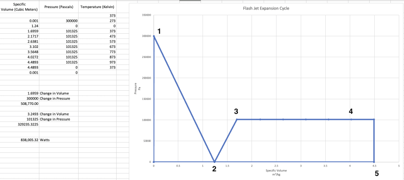
I'm developing a thermodynamic cycle that transfers existing heat to generate steam. The heat transfer includes reusing the latent heat of condensation harvested at the condenser to heat the working fluid. Normally, this is not possible because the condenser is not the hottest point in the cycle and therefore any heat harvested cannot be transferred back into the working fluid which is hotter at any point in the cycle before the condenser. This limitation does not exist in the cycle I'm developing. Unlike a Rankine Cycle which generates high temperature heat for the generation of superheated steam, this cycle uses and re uses low temperature heat for the production of steam.

I'm looking for a mechanical engineer who'd like to be a cofounder for a green tech company based on this cycle. Preferably you live in CA or would be willing to move to CA at some point after funding is achieved and you are receiving a salary. The skills needed to prove the viability of the cycle and develop it are:

CFD
Heat Balance
MATLAB
Simulink
CAD
Turbomachinery
Electrical Engineering knowledge is a plus

I am familiar with OpenFOAM, Fusion360, MATLAB and other tools.

Please respond only if you are interested, have the skills, and are willing to become a cofounder.
 
Replies continue below

Recommended for you

TiCl4 (Chemical) said:
OP also hasn't addressed my issue with the amount of available heat transfer area. Still an impossible idea.

Thank you for the comment. The heat transfer is provided by steam entrainment into the flow of the water. This method is facilitated by the low pressure created by the accelerated fluid. By entraining steam into the flow, ample heat is added to the flow, and nucleation sites for cavitation are also provided.

On another note, the flow rate you used from the spreadsheet was for a much larger flow and I mentioned this in my post with the spreadsheet.

"My current design goal for a prototype is 300 kPa, but with a lower flow rate so the diameter of the Venturi is smaller than this screen capture. But you can see from this screen capture how the inlet pressure affects the throat pressure."

Everything else is based on a 1 liter / second flow rate. However, you are correct that there is not enough surface area - even at the 1 liter per second flow rate.

 
IRstuff (Aerospace) said:
Waste heat quality is never as good as the initial heat source's. Fourier's Law says that heat flows from a hotter source to a cooler destination, so trying to get waste heat into the main process stream is very difficult; you bandy about amounts of heat, but have never addressed the temperature differences relative to the supposed pressure differential. Trying to drop the pressure that low is a non-trivial exercise, and I think that if you do the math, the amount power required to depressurize your fluid will be in excess of any savings you gain from using the waste heat. By thinking that you have a net efficiency, you are essentially peddling perpetual motion.

Thank you for your comment, IRstuff. Waste heat quality isn't as good as the initial heat source, but it is heat and it's temperature can be augmented by adding additional heat from an outside source. Getting that heat to transfer back into the system though is the challenge. By using a flash process to create the steam, the temperature of the fluid can be controlled and the goal is to create water vapor at a lower temperature so the heat from condensation can be transferred to it.

Dropping the pressure doesn't require as much energy as long as it's done in the flow of water. I included links to studies on creating negative pressure in a Venturi. To achieve the requirements - 300kPA and 1 liter / second flow rate - roughly 160kW of electricity are used by the pump.
 
TiCl4 (Chemical) said:
Haruosan,

You do NOT have enough surface area to complete the heat transfer in the venturi. It is a simple fact.

TiCl4,

Thanks again for your input. My apologies if I'm annoying you, but I do appreciate your input.

You are correct, there isn't enough surface area to transfer heat to the fluid via conduction. I mentioned this in my previous post. The method to inject the appropriate amount of heat is steam entrainment. Of course, you may also mean that even with steam entrainment there isn't enough surface area, but the surface area of heat transfer is increased greatly with the injection of very small bubbles of steam into the liquid flow. Every bubble becomes a surface with area for heat transfer. These bubbles also become nuclei that will augment the flash effect. The enthalpy of 350 grams of steam should be enough. I also know that even if saturated steam is not created at the Venturi, any remaining water can be vaporized in the boundary layer turbine where a much larger amount of heat energy will be applied and there will be a lot more surface area.

If the goal is compelling enough, engineer to the goal. The result may be it will never work, but until then...
 
And where, exactly, is this mystery steam coming from? From your comments, you have 3 mass flows coming out of the "condenser heat exchanger" - one going to the reservoir and the other two going to the venturi and turbine. The "venturi" stream is injected into the venturi, but what happens to the turbine? If this is injected into the process-side, it cannot be used to power the turbine. Thus, the turbine needs another energy input.

You state that the turbine is used to pull vacuum on the venturi. Thus, it must be a powered turbine - it cannot be used to simultaneously do work on the fluid and create energy.

Please provide the flow diagram with example flow rates.

Also, you do not have enough time to inject, mix, and create enough bubbles in a venturi throat to achieve any significant surface area. Not physically possible.
 
TiCl4 (Chemical) said:
And where, exactly, is this mystery steam coming from? From your comments, you have 3 mass flows coming out of the "condenser heat exchanger" - one going to the reservoir and the other two going to the venturi and turbine. The "venturi" stream is injected into the venturi, but what happens to the turbine? If this is injected into the process-side, it cannot be used to power the turbine. Thus, the turbine needs another energy input.

You state that the turbine is used to pull vacuum on the venturi. Thus, it must be a powered turbine - it cannot be used to simultaneously do work on the fluid and create energy.

Please provide the flow diagram with example flow rates.

Also, you do not have enough time to inject, mix, and create enough bubbles in a venturi throat to achieve any significant surface area. Not physically possible.

TiCl4,

The steam production is a flash process that occurs within a flow of water, imposed by creating a zone of low pressure inside a specially designed nozzle. The nozzle could be as simple as a Venturi. The lower pressure creates a super heat condition (not superheated steam, but heat above the vapor pressure).

Reservoir--->Pump--->Venturi--->Exit
Water-Water-Water-water----Two Phase Flow or Saturated Steam

[ul]
[li]0 Pascals can be achieved forcing water through a constriction[/li]
[li]With high superheat (heat above the vapor pressure - not superheated steam)flashing occurs[/li]
[li]The flash process occurs in 200 microseconds[/li]
[li]The ideal contraction ratio for the nozzle is .65[/li]
[li]The length of the Venturi / nozzle throat does not affect pressure - a low pressure condition can be maintained even if the throat is 1 meter long[/li]
[li]This setup is used in the study of cavitation and super cavitation[/li]
[li]This setup is also used in Flash Atomization[/li]
[li]Flash Atomization studies illustrate that the flash process occurs in the nozzle so the exit does not have to be in low pressure[/li]
[li]several studies describe "Fully flashing Flows" when water temperature is considerably higher than vapor pressure (super heated)[/li]
[li]At the 1 liter/second flow rate, velocity is 24 m/s[/li]
[li]At 24 m/s the throat can be 5mm in length, but could be even longer[/li]
[li]Even if fully saturated steam is not created at the nozzle exit, the effect of the cavitation bubbles in the flow highly atomizes the water to enable more efficient heat transfer through increased surface area. The water can be fully vaporized, after the fact, in the boundary layer turbine which can have a large amount of surface area offered by the disks of the turbine[/li]
[/ul]

This is a cavitation experiment with water at room temperature:
Screenshot_2024-01-05_at_2.17.34_PM_otmsiu.png

This is a flash atomization study illustrating a fully flashing flow at high superheat
Screenshot_2024-01-05_at_2.16.16_PM_prdwnz.png


Let's get passed this and I can fill you in on the rest of the process.
 
3DDave (Aerospace) said:
Where is the rest of that paper?


Venturi Structural Parameters

Transition of cavitating flow to supercavitation within Venturi nozzle – hysteresis investigation

Cavitating Flows

Flash Evaporation Phenomenon and Resulting Shock Wave

I tried to stick to studies of flash occurring "in nozzle" rather than flash occurring upon nozzle exit into a low pressure chamber.

Initially I researched cavitation that views this phenomenon within the context of fluid dynamics, but for me it didn't really explain what was happening and didn't include much thermodynamic information - most was based on cavitation number only. But, this really is a thermodynamic event. The phase change of water depends on vapor pressure and thermal energy. For flashing, water at 100C (373k) contains roughly 60% of the heat required to create saturated steam. The remaining 40% can be added during the steam production step of the process or within the boundary turbine. Either way, the flash process breaks up the liquid flow and increases surface area. If the turbine is pre-heated and continually heated, the remaining heat can be transferred in the turbine.

The whole process is about doing the steam cycle process in a different way and quite the opposite of a Rankine cycle. In traditional steam cycles high temperature heat and pressure are used to create steam with increased enthalpy and releasing it to a turbine that captures the energy from kinetic force - most of the enthalpy of superheated steam is in the phase change, not the superheat. Instead, the process is the opposite using a low-pressure dominant process that flashes water into vapor and then heat is added. The benefit is you are directing your heat at a phase of water that has a specific heat that is half that of liquid water. And, most importantly, you can transfer the heat from the condenser to the vapor, allowing you to reuse the heat instead of wasting it. It isn't perpetual motion, but you could maintain a 1 kg flow of steam with much less energy. Will it have as much energy as superheated steam? No. But it could come close if you heat the steam in a large turbine or series of turbines to 300C, 400C, 500C. And, it would take less energy.
 
OK. It comes out of the flash evaporator at near 0 Pascals as your examples have the nozzle expanding into a vacuum chamber. How is that used to drive a turbine?

Are any of the examples used to drive turbomachinery? The last one is for distillation, so no power is available from the process.
 
OP, one of the larger misses in your understanding here seems to be that pressure is the key driver of work extracting devices like turbines, not the temperature or degree of superheat.

A Rayleigh cycle doesn't work very well without the boiler feed pumps to boost the pressure of the feedwater up before it is heated into steam because low pressure steam, even if very superheated, simply isn't useful for driving a turbine. I mean that quite literally - feed superheated vapor of any description into a turbine at near zero absolute pressure and the turbine simply will not spin. It's the pressure (or inlet-outlet differential, if you prefer) of the steam that drives the turbine, not the temperature. Steam is certainly more useful coming into a turbine when superheated, but this is only because more work can be extracted (that is to say lower outlet pressures can be achieved) before liquid condensation starts to wreck your turbine.

Neglecting the fact that a heat engine must reject 'waste' heat into a cold reservoir by the basic laws of thermodynamics, the method you have devised to attempt to eliminate waste heat rejection requires very low temperatures elsewhere in the cycle to push the rejected heat into. Unfortunately by lowering the pressure so drastically to get cold superheated vapor you have completely robbed the fluid of any meaningful ability to do work.

 
3DDave (Aerospace) said:
OK. It comes out of the flash evaporator at near 0 Pascals as your examples have the nozzle expanding into a vacuum chamber. How is that used to drive a turbine?

Are any of the examples used to drive turbomachinery? The last one is for distillation, so no power is available from the process.

When I posted the links to the papers, I mentioned:

"I tried to stick to studies of flash occurring "in nozzle" rather than flash occurring upon nozzle exit into a low pressure chamber."

One of the papers mentions exit into a flash chamber, the others do not. Keep in mind the zone of 0 Pascals is created in the throat of the Venturi and it doesn't move. The water passes into the zone and is then superheated (because of drastically lowered vapor pressure), upon which it expands and then exits the zone of 0 Pascals, but it does not exit the Venturi at 0 Pascals. The flow rate of the water is 1 liter per second with a velocity of 24 m/s through the throat of the Venturi. The diameter of the exit is 12mm. The flow rate of the steam will be 1 kg/s through a pipe with an area of 0.0001131 m^2. 1/.0001131 = 8,841 m/s. This seems a bit high to me. Even without calculating the velocity, we should be able to intuitively understand that a 1 liter per second flow of water being pushed by 300 kPa through a Venturi, then expands 1600 times into vapor / steam would have a velocity greater than the water, higher than 24 m/s.
 
3DDave (Aerospace) said:
Returning heat to the turbine makes the turbine hotter; but if that heat is just transferred out as heat at the exhaust of the turbine it has done no additional work. The heat is being recirculated, but it isn't being used to produce work. If it did work, the temperature would be even lower.

3DDave,

I think you are right. If the heat is just exhausted as waste it hasn't done any work. I don't know at this point how much of the heat will be transferred to the steam as temperature or as work. I do know that when you heat a gas, it expands and when a gas expands in a boundary layer turbine, the turbine will spin faster. It may be that some of that heat energy is used as work and some of it is used to increase temperature. The steam will expand in the turbine and I think it will also increase in temperature which also increases the pressure within the turbine. Then, when the gas exits the turbine through a constriction, it will accelerate and cool down. That would mean the heat was used for work, not temperature. So, maybe some of the heat is lost due to that. Will it ever heat up? I don't know, that will have to be tested. If the steam never heats up because it always cools down during the exit from high to low pressure - and all the heat was used for work, turning the turbine - then the steam will need to be heated to at least over 100C after the turbines and before it enters the condenser. Will heating a series of turbines and then heating the steam to 100C use less energy than a traditional steam plant? We won't know until we test it. Considering steam has a specific heat that is half that of water it may indeed be more efficient.
 
GBTorpenhow (Mechanical) said:
Still not sure if you are taking the piss here or not OP, but a thermodynamic cycle on a PV plot should be a closed shape, no? You could also easily see the amount of net work in such a plot.

Taking the piss, Lol. I don't know if I am yet, either. Yes, the thermodynamic cycle on a PV plot should be a closed shape. You'll notice the final volume, farthest to the right .001, is also the starting volume, which means it's a cyclic loop and would be a closed shape. I wasn't able to get my spreadsheet to make a closed shape. .001 is 1 liter of water and the volume increases as it flashes into steam, then expands from being heated, increasing the pressure within the turbine. I have calculated the amount of work.

2.61158 Change in Volume
250000 Change in Pressure
652,895.00

652000 Watts
 
haruosan said:
You'll notice the final volume, farthest to the right .001, is also the starting volume, which means it's a cyclic loop and would be a closed shape.
You... overwrote the value of one of the points on the x axis? That's an interesting approach. So your cycle PV plot actually looks like this?
Screenshot_2024-01-01_at_6.06.52_PM_pzu0fo_syrbam.png

Seeing the problem here?
 
GBTorpenhow (Mechanical) said:
You... overwrote the value of one of the points on the x axis? That's an interesting approach. So your cycle PV plot actually looks like this?

I didn't overwrite any values. The spreadsheet I used displayed the values in a chart as it is shown instead of closing the loop.

Your PV Plot doesn't even reflect the largest expansion from .001 to 1.249. Even if I calculate the amount of work from the constant pressure of 101.325 kPa and a change in volume of the steam of 2.61158, the amount of work is 265kW.

What I will do is provide a more accurate PV diagram

 
What I meant by 'overwrote' is you are showing a line graph with arbitrary spacing on the x axis, not an x-y plot with both axes to scale, hence my confusion.

Labels of the state points in relation to the PFD would help as well, as your state points aren't making any sense to me. Steam at 250 kPa and 2.6 m3/kg is at something like 1400K. I don't see anything close to that temperature on your PFD.
 
Here are a new PFD and PV Diagram with state points labeled. I increased the temperature and only have heat being added at the turbine. The isobaric portion has heat added at the turbine. Additional heat is added at 4 and should not add to work, but I've left it for this exercise. I'm trying to get a rough ball park of the amount of work achievable. For the expansion in the turbine, I kept the pressure constant to see how much the volume of the steam increases when the heat is added. The volume of the steam is specific volume at 1 atm and heat added from 273K - 868K.


Screenshot_2024-01-16_at_9.56.46_AM_jtnacd.png

Screenshot_2024-01-15_at_7.13.49_PM_fnpjt9.png
 
OK - low pressure vapor enters the turbine at 0 C and then exits the turbine under high pressure and high temperature where it is further heated before going to a heat exchanger where it is cooled to liquid.

Is that right so far? If not - PUT FLOW DIRECTION ARROWS ON THE FLOW DIAGRAM.
 
3DDave (Aerospace) said:
3DDave (Aerospace)16 Jan 24 14:39
OK - low pressure vapor enters the turbine at 0 C and then exits the turbine under high pressure and high temperature where it is further heated before going to a heat exchanger where it is cooled to liquid.

Is that right so far? If not - PUT FLOW DIRECTION ARROWS ON THE FLOW DIAGRAM.

3DDave,

Thank you for the suggestion. I put flow direction arrows on the PFD. I also added the liquid flow rate and the velocity of the vapor upon exit of the Venturi. The flow rate of the water is 1 liter per second with a velocity of 24 m/s through the throat of the Venturi. The diameter of the exit is 12mm. The flow rate of the steam will be 1 kg/s through a pipe with an area of 0.0001131 m^2. 1/.0001131 = 8,841 m/s.
 
Are these pressures absolute or gauge? If absolute, then how does the condensate exist as liquid at 0 abs pressure and 373K? If gauge, temps are way off (1.659 m3/kg @ 101.325 kPag is 730K).

What causes the pressure change between 2 and 3? 4 and 5?

How does the turbine spin if there is no pressure differential across it?

Do you think it is realistic to have vapor at the turbine inlet with a fluid velocity of 8,851 m/s? What is the speed of sound for this fluid at those conditions?

 
Status
Not open for further replies.
Back
Top