Continue to Site

Eng-Tips is the largest engineering community on the Internet

Intelligent Work Forums for Engineering Professionals

  • Congratulations MintJulep on being selected by the Eng-Tips community for having the most helpful posts in the forums last week. Way to Go!

Thermodynamic cycle that can reuse latent heat of condensation 8

Status
Not open for further replies.

haruosan

Computer
Jun 27, 2023
41
I'm developing a thermodynamic cycle that transfers existing heat to generate steam. The heat transfer includes reusing the latent heat of condensation harvested at the condenser to heat the working fluid. Normally, this is not possible because the condenser is not the hottest point in the cycle and therefore any heat harvested cannot be transferred back into the working fluid which is hotter at any point in the cycle before the condenser. This limitation does not exist in the cycle I'm developing. Unlike a Rankine Cycle which generates high temperature heat for the generation of superheated steam, this cycle uses and re uses low temperature heat for the production of steam.

I'm looking for a mechanical engineer who'd like to be a cofounder for a green tech company based on this cycle. Preferably you live in CA or would be willing to move to CA at some point after funding is achieved and you are receiving a salary. The skills needed to prove the viability of the cycle and develop it are:

CFD
Heat Balance
MATLAB
Simulink
CAD
Turbomachinery
Electrical Engineering knowledge is a plus

I am familiar with OpenFOAM, Fusion360, MATLAB and other tools.

Please respond only if you are interested, have the skills, and are willing to become a cofounder.
 
Replies continue below

Recommended for you

MintJulep,

Yes, I have done a heat balance.

I like the discourse and appreciate your efforts to show me why this doesn't have some merit worth pursuing. However, you haven't yet showed my why its not. You sarcastically mentioned that I have no need for a cold reservoir because all the waste heat is "recovered" by the condenser...simply because I drew an unlabeled line. I did state what that component is: It's a 4000m^2 surface area with thermal heat pipe technology to absorb and transfer heat to the the flash reactor and the turbine. Heat transfers because there is a 200 degree temperature differential between the condenser and the flash reactor and a smaller difference between the condenser and the turbine.

Can you do me a favor and let's take one step in the process at a time and walk through it.

From starting at the reservoir, what is the first step you feel will not work?
 
I'll say it again, clearer this time: water will not exist as useful vapor at -50C.

OP said:
The heat rejection happens at the flash reactor and the turbine.
OP said:
The working fluid is vaporized in a flash process which produces a cold vapor - this is the cold reservoir
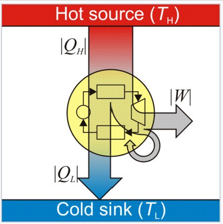
The cold reservoir must be external to the heat engine itself (yellow circle in the below). The working fluid can't also be the cold reservoir.
Screenshot_2023-11-06_210329_d02apn.jpg
 
harosan said:
However, you haven't yet showed my why its not.

You started this thread with a solicitation for an engineer with a salary.

I'd be happy to explain the details to you for an exorbitant fee. Others here may be more qualified than I, or have lower rates, or both.
 
GBTorpenhow,

Thank you for the Carnot heat engine diagram.

You mentioned that water can't exist as "useful" vapor. Does this mean you've changed your mind that it can exist at -50, but it is just not useful?

I disagree though because the force and shockwave produced from a flash vapor event has some power and the resulting gas can also be heated so it expands and work can be achieved by capturing this expansion. By using flash vapor a low temperature vapor can be produced. If you want it to be 1C, then let's make it 1C as it will still be a good heat sink for the condenser, but able to exist as vapor because it's not below freezing.

The cold reservoir is what ensure heat transfer. We generally think of it as external to the heat engine because our condenser is always colder than the heat source.
 
OP said:
You mentioned that water can't exist as "useful" vapor. Does this mean you've changed your mind that it can exist at -50, but it is just not useful?
No, I added useful because while not realistically achievable, hypothetically at near zero pressure if you had a couple single water molecules drifting about in an otherwise empty void, it could be argued that this could be called water vapor, at essentially any temperature. But that isn't useful because at 0C and below the pressure has to be near zero for vapor to exist. A hard vacuum isn't useful as a working fluid for a power cycle.

OP said:
If you want it to be 1C, then let's make it 1C as it will still be a good heat sink for the condenser, but able to exist as vapor because it's not below freezing.
You are missing the point, but OK, 1C it is. NIST tells me that the vapor pressure of water at 1C is 650 Pa. As a reminder, that means that at 1C, at any pressure above 650 Pa, water will not exist as vapor. For reference, normal atmospheric pressure is ~101,300 Pa. What work do you think you are going to do with a working fluid at a pressure that is basically a laboratory grade vacuum? Turbines run on pressure differential. You have depicted a turbine that somehow runs on near zero inlet pressure.

OP said:
Normally, the heat from condensation is lost to the cooling fluid and thus the environment. However, if your cooling fluid is the working fluid, then the heat is reused, not lost to the environment.
Here is where you are saying to us "this is a perpetual motion machine". You can't eliminate the waste heat rejection (Q_L) from the heat cycle, this would be a violation of the basic laws of thermodynamics.
 
GBTorpenhow,

Screenshot_2023-11-07_at_10.48.51_AM_brdwy4.png


When you pump water through a constriction, the pressure through the throat is lowered. Essentially, a low pressure zone is created at the Vena Contracta and through the length of the throat of the Venturi. Liquid flowing through this low pressure zone will form an annular flow with gas in the center and liquid against the walls. If the pressure is low enough and heat is added along the throat, saturated vapor will be produced. This zone of low pressure is only momentary and the egress of the Venturi is atmospheric pressure (or at least something other than the low pressure of the throat). Also, the supercavitation jet created through the throat will exit downstream with a shockwave, force, and compression. Although the pressure is low at the throat, this is not maintained anywhere other than the throat. The shockwave created by the 1 liter per second flow of water and the subsequent 1600 X expansion of the water into steam creates a force that can power a turbine. Further heating of the gas as it flows through the turbine also adds force.

Heat can be added to the throat area to account for the remaining latent heat of vaporization. The sensible heat contains 1,323 kJ/kg so another 932kJ/kg for fully saturated steam and an additional amount of heat to raise the temperature of the resulting vapor.

Flash Vaporization Creates shockwave and Useful Compression

Effect of Structural Parameters of Venturi


Here's a quick comparison

If you had 1 liter of water at 100C and wanted to phase change it into fully saturated steam at 100C, you will need to add this much thermal energy:

Method 01 total heat added: 2,256,000 J/kg.

If you had 1 liter of water at 100C and you dropped the vapor pressure to transform the heat already in the water into latent heat of vaporization and added additional heat to produce 100C saturated steam:

1,323,000 J are already contained in the water
932 kJ/kg - remaining latent heat of vaporization
744.5 kJ/kg - raises temper of vapor to 100C

Method 02 total heat added = 932 kJ + 744.5 kJ = 1,676.5 kJ/kg

Method 02 requires roughly 25% less energy to arrive in the same place. Why is that?

Oh, and just as a side note: No it doesn't take less heat for the phase change because that would violate the laws of physics. The total amount of heat added for phase change is still the same at 2,256 kJ/kg it's just that 1,323 kJ/kg came from the sensible heat.

By directing sensible heat to latent heat of vaporization and then heating the working fluid when it is in a state with the lowest specific heat and is therefore the easiest state of water to change temperature, it is a more efficient process. Keep in mind the flash process occurs in less than 200 microseconds. The heat transfer is very efficient and extremely fast. This is why a shockwave is produced.
 
In your method 2, what are the starting an ending pressures for the first step (flashing though an orifice)? How do you get the pressure back up such that the steam is saturated at 100C?

If you add pressures to your example and the PFD you might start to understand why this won't work.
 
GBTorpenhow,

Thank you, again for your response and helping.

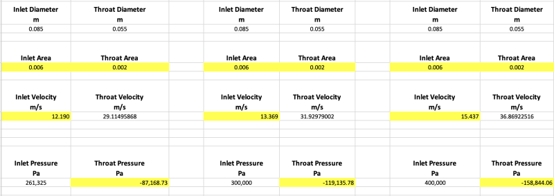
In method 02, the pump creates a pressure of at least 261,325 Pa upstream of the Venturi. Several studies have shown that with a .65 contraction ratio in the throat of the Venturi and an inlet / outlet pressure difference of at least -160 kPa, there will be a zone of low pressure of 0 Pa in the Vena Contracta. A higher differential will create negative pressure (not just gauge, but more than -101,325). My current design goal for a prototype is 300 kPa, but with a lower flow rate so the diameter of the Venturi is smaller than this screen capture. But you can see from this screen capture how the inlet pressure affects the throat pressure.

Screen_Shot_2023-11-07_at_3.00.49_PM_jw6rng.png


I don't yet know the pressure at the outlet of the Venturi before the vapor enters the turbine, but I think it will be a bit lower than atmospheric for two reasons:

1. The steam condensing further upstream will create a slight vacuum.
2. The turbine will create a slight vacuum at its inlet too when gas is expanded (heated) in the turbine. In a boundary layer turbine, when the gas is heated and the gas expands, it forces the turbine to spin faster with the expansion force closer to the axle which makes the periphery spin faster and creates a vacuum.

I'll add pressures to my PFD to see if I can find any discrepancies.
 
Surely negative pressures can only exist at negative temperatures, less than 0K, right?

OP said:
Many studies show that water will resist cavitation to as high as -20 Megapascals.
This sounds fascinating, can you post a citation so I can read about this? That's a lot of negative pressure. Is that -20 MPa gauge or absolute?

I suppose with a high enough negative pressure, quite a lot of energy could be extracted with a turbine... but it would be negative power which would be an issue. Have you figured out how you are going to convert the negative power into positive power?
 
GBTorpenhow,

Here is a study that discusses the predicted cavitation pressure of stretched water at -100 to -200 MPa, but experiments have shown it to be achieved at -30 MPa. I don't remember if it is gauge or absolute, but think it is absolute.


I do believe you are correct about negative pressures existing only at negative temperature. At 0K which is 0 Pa, There no longer is any temperature remaining. If there were the heat would instantly affect any hydrogen bonds and, if it were enough heat, would break the bonds. However, with the lack of any heat and with hydrogen bonds remaining, the only way to sever those bonds, another force is required which is pressure - negative pressure. I do believe this is why scientists say that negative pressures act like negative temperature. The force of the pressure acts like heat to a hydrogen bond.

Not Scientific Article About Negative Pressure and Temperature

Keep in mind, I am NOT relying on negative pressure for the flash reactor. I am only achieving 0 Pa. That zone of 0 Pa pressure though, only exists in the throat of the Venturi. When the water passes through this zone, it cavitates and flashes, the wateer expands 1600 x and a shockwave is produced. The pressure at the egress of the Venturi is not negative. Also, the pressure in the turbine is also not negative (as I stated earlier it may be less than atmospheric, but not negative in absolute terms). So, no, there is no negative power to turn into positive power. The vapor flashes out of the downstream outlet like a jet - that's where the power comes from.
 
OP said:
1. The steam condensing further upstream will create a slight vacuum.
2. The turbine will create a slight vacuum at its inlet too when gas is expanded (heated) in the turbine. In a boundary layer turbine, when the gas is heated and the gas expands, it forces the turbine to spin faster with the expansion force closer to the axle which makes the periphery spin faster and creates a vacuum.
Ah, I see. You are using the shock wave to enhance the intermolecular hydrogen bond forces to allow the vapor downstream of the turbine to influence the upstream normal and swirl component velocity vectors on the axial face of the turbine discs. Very interesting.

Looking forward to seeing the PFD annotated with pressures and specific enthalpies.
 
I spent some time sailing a "modern" steam ship. There are 3 process streams for various uses around the plant. 150 psi, 35 psi, and 7 inHg pressures. The condenser is at 28.5 inHg.

I made some observations in that time. Firstly, pressure reducing valves are an incredible waste of energy. When the engine is idle, the PRVs supply the system but as the ship comes up to speed there are extraction points in the turbine to supply the 3 low pressure systems. This way the engine is extraction power from the expansion so the energy is no longer lost.

The 35 psi system is also often called auxiliary exhaust though that is no longer true. Steam auxiliary turbines are not very efficient when exhausting into 35 psi. All auxiliaries with the exception of the feed pumps are electric on a modern ship. The boiler feed pumps exhaust into the main condenser for better efficiency. Even steam eductors (orifice) for non-condensible removal are all electric powered now.

The 7 inHg extraction is used to boil water at ~150°F in the evaporator. The condenser for the evaporator is cooled by the condensate from the main condenser in the 1st stage feed heater.


Some takeaways, you're only losing of you have an orifice or pressure reducing valve.

Don't put back pressure on your turbines. It kills the Carnot cycle efficiency.

What can you do with 95° water? Not much.


Maybe you could use a fan to maintain vacuum on the turbine while increasing the pressure to condenser the steam? The condensate might be hard on the fan at the high specific speeds required.
 
Okay, this is definitely a pie-in-the-sky idea.

You propose accelerating through a venturi to drop pressure low enough to vaporize water,AND, before the vapor decelerates in the outlet, you add a ton of energy to keep it in the vapor phase.

How in the world are you expecting to transfer enough energy through a venturi throat? You must have a minimum surface area for that heat transfer, but increasing the surface area will mean an increasing throat size, even if you corrugate/fin the pipe. That would drop your velocity and kill any vaporization.

This is a thermodynamic impossibility.
You are "adding" 932kJ/kg in the throat to maintain saturated vapor condition. Let's do a brief bit of math:

Using the info from your spreadsheet:
Inlet Velocity: 12.2 m/s
Inlet Area: 0.00567 m2
Liquid Flow: 0.069 m3/s, or ~69 kg/s

Heat "Added" 932 KJ/kg
Heat Xfer Required: 64,468,000 J/s

Estimated heat transfer area of throat (throat length = throat diameter): 0.0227 m2

dT available: 450 K (being generous, assuming -50 C to 400 C throughout the Hx area based on your "sketch"

Required Hx Coefficient = 64,468,000 / (450*0.0227) = 6,311,711 W/m2K. This is ~3,000 times higher than best case heat transfer between fluids.

Or, going at it another way...
Assume a stupidly high Hx Coefficient: 4,000 W/m2K

Required area: 64,468,000 / (4,000*450) = 35.8 m2. Available area: 0.0226 m2. You have 0.063% of the area needed.

No matter how you calculate it, you are 3-4 ORDERS OF MAGNITUDE off of the physical requirements to transfer this heat!

All, please stop responding to this thread, this is another one of those "Gel Silica" threads...


This is not the first time I'm coming across this idea of using pressure anomalies in venturis operating at supersonic flow conditions. One oil/gas major has / had a license ( which was parceled out to a third party licensee) for gas dehydration in offshore gas fields by operating venturis at supersonic flow, on the assumption that hydrate formation in the venturi would not be possible in the low pressure supersonic flow and pressure recovery region. Venturis and downstream condensate-hydrate separation vessels were all hot oil jacketed. They went so far as to install and operate a >USD500million offshore facility with this concept. Some years later, we heard of operator complaints that they were having to inject large amounts of methanol into the venturis to stop hydrates / ice from bunging up the venturis and downstream condensate separation vessels. To rub more salt into the wound, booster compression had to to be advanced by many years to keep the JT mode of dehydration at these venturis going. Attempts to sell an "improvised version" of this concept for yet another field development fell flat - I was at the review meetings for this Mark II version with the licensor.
Your PFD doesnt show any of these detailed sub unit operations that you later declared, and it is missing some crucial pressure / temp / enthalpy details also. In any case, good luck with your attempts to market this concept. You'll need a good legal team to keep the wolves off you when they come a looking.
 
My issue that I haven't seen addressed yet is that your gasses turn the turbine, which the turbine then heats up the gasses, which then turn the turbine even faster. That in itself is circular nonsense. If that worked you could just keep that principle going until your gases were moving at the speed of light and you had achieved infinite energy.
 
lucky-guesser said:
My issue that I haven't seen addressed yet is that your gasses turn the turbine, which the turbine then heats up the gasses, which then turn the turbine even faster. That in itself is circular nonsense. If that worked you could just keep that principle going until your gases were moving at the speed of light and you had achieved infinite energy.

No, it's not circular nonsense. Heat is applied at the turbine to transfer heat to the gas within the turbine. When heat is applied to the gas within a boundary layer turbine, the gas expands and forces the turbine to spin faster. The heat, at first, is from an outside source, but after the first cycle, latent heat is transferred from the condenser to the turbine. And, no, this isn't perpetual motion and the heat feeds itself somehow, magically. Far from it. Latent heat is re-used, but additional heat is still required. However, since latent heat reuse makes up a good majority of the heat energy, the additional heat energy is much less. Even so, the same amount of heat required for latent heat of vaporization is used for phase change. It's just that a good chunk of it is re-used.

PV Diagram For 1 second of the cycle - 1 liter per second flow of water:
Screenshot_2024-01-01_at_6.06.52_PM_pzu0fo.png
 
Returning heat to the turbine makes the turbine hotter; but if that heat is just transferred out as heat at the exhaust of the turbine it has done no additional work. The heat is being recirculated, but it isn't being used to produce work. If it did work, the temperature would be even lower.
 
Still not sure if you are taking the piss here or not OP, but a thermodynamic cycle on a PV plot should be a closed shape, no? You could also easily see the amount of net work in such a plot.
 
OP also hasn't addressed my issue with the amount of available heat transfer area. Still an impossible idea.
 
Waste heat quality is never as good as the initial heat source's. Fourier's Law says that heat flows from a hotter source to a cooler destination, so trying to get waste heat into the main process stream is very difficult; you bandy about amounts of heat, but have never addressed the temperature differences relative to the supposed pressure differential. Trying to drop the pressure that low is a non-trivial exercise, and I think that if you do the math, the amount power required to depressurize your fluid will be in excess of any savings you gain from using the waste heat. By thinking that you have a net efficiency, you are essentially peddling perpetual motion.

TTFN (ta ta for now)
I can do absolutely anything. I'm an expert! faq731-376 forum1529 Entire Forum list
 
Status
Not open for further replies.

Part and Inventory Search

Sponsor