GBTorpenhow (Mechanical) said:
Any prospective employee worth their salt will likely see the following as red flags:
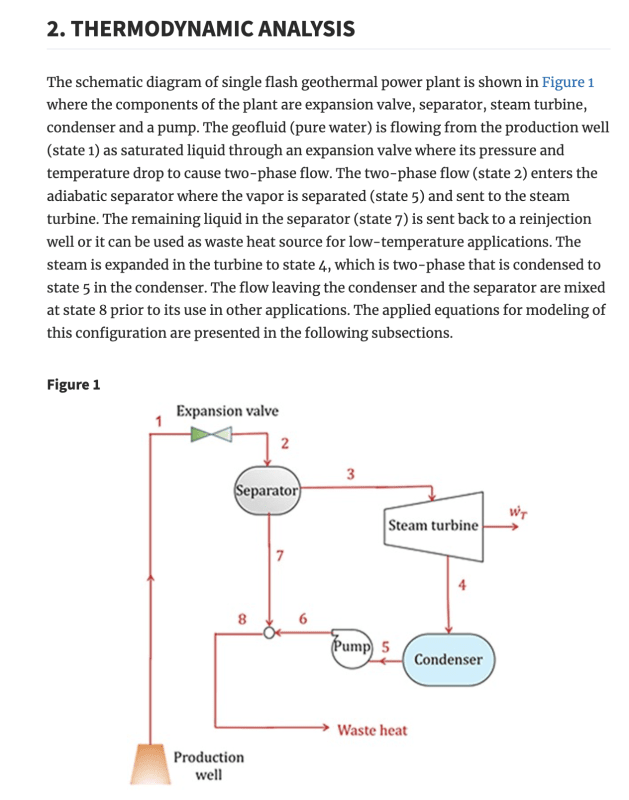
- A power cycle with an expansion valve immediately after a pump
- A power cycle where the only external heat input is applied after the work extracting device
- A work extracting device that is claimed to heat up the fluid stream
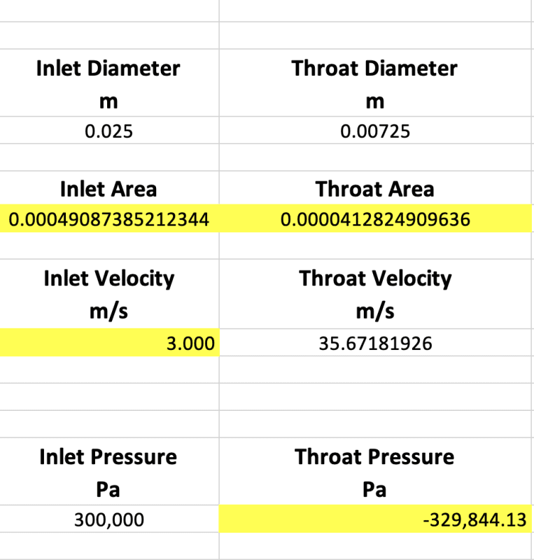
- Straight faced references to negative absolute pressures
- Liquid being conveyed to the inlet of a pump at 0 Pa absolute and 100C
- Vapor velocities 3-4x sonic velocities
Practical/technical issues aside, the fundamental conceit of your idea - that instead of rejecting condenser heat to atmosphere it can be used elsewhere in the cycle - is a violation of the laws of thermodynamics.
"It is impossible to construct an engine which will work in a complete cycle, and produce no effect except the production of work and cooling of a heat reservoir." (Planck)
Any prospective employee worth their salt will likely see the following as red flags:
- A power cycle with an expansion valve immediately after a pump
Geothermal power plants use the natural pressure of geothermal steam to force hot water through an expansion valve. Natural pressure or a pump, there really isn't a difference except you have to ensure you have the correct head for the pump inlet so cavitation doesn't occur through the pump.
- A power cycle where the only external heat input is applied after the work extracting device
The heat input is applied at the work extracting device (or series of extracting devices). When heat is applied to a gas cycling through a boundary layer turbine it expands and forces the turbine to spin faster as well as adds torque.
- A work extracting device that is claimed to heat up the fluid stream
The work extracting device itself doesn't heat up the fluid stream, but instead heat is applied to the work extracting device which, in turn, heats the working fluid.
- Straight faced references to negative absolute pressures
What's wrong with negative pressure? Do you still believe that negative pressure in fluids do not exist?
Thermodynamics of Negative Pressures in Liquids
Exploring water and other liquids at negative pressure
The Physics of Negative Pressure
I believe it's related to molecular bond forces such as hydrogen bonds in water. Even when pressure and temperature are 0 there's no longer any heat to break hydrogen bonds and the only force left to counteract the molecular forces is stretching or negative pressure. However, it's difficult to study since it forces liquids into a metastable state which is forced to equilibrium.
- Liquid being conveyed to the inlet of a pump at 0 Pa absolute and 100C
With the right head, it's possible
- Vapor velocities 3-4x sonic velocities
I don't believe the vapor reaches these speeds, for various reasons but, as many papers describe there is a shockwave force when water flashes into steam. the force created high velocity. How high, I don't yet know.
Practical/technical issues aside, the fundamental conceit of your idea - that instead of rejecting condenser heat to atmosphere it can be used elsewhere in the cycle - is a violation of the laws of thermodynamics.
I don't believe it is a violation of the laws of thermodynamics. Take for example, condensate reuse. How is heat from a previous cycle reused in the next cycle? How about we use the latent heat of condensation to heat water. Are you suggesting that the heated water could never be reused in the same cycle the heat came from?How about we use the latent heat of condensation to heat steam. Are you suggesting that the heated steam could never be reused in the same cycle the heat came from to heat the boiler feed water?Heat transfers from hotter to colder - it doesn't matter where the hot or cold is.
"It is impossible to construct an engine which will work in a complete cycle, and produce no effect except the production of work and cooling of a heat reservoir." (Planck)
The important part of Planck's statement above is the suggestion that heat must be shed to a cold reservoir. The heat has to transfer from hot to cold in order to create work. Heat transfers from hot to cold, it doesn't matter where the heat or the cold is.