Eng-Tips is the largest engineering community on the Internet

Intelligent Work Forums for Engineering Professionals

Third Pump - Significant decrease in flows 8

Status
Not open for further replies.

catplank

Civil/Environmental
May 1, 2020
15
0
0
AU
Hello All,

I’m a little stumped the following… any able to offer any insight?

Normal Operating conditions 2x pumps in parallel. Third pump kicks in on level control. When third pump kicks in its flow/current in the middle pump (pump 2) is significantly lower.

Pump 1 & 3 = 40L/s @120A
Pump 2 = 30L/s @100A

If pump 2 is operating under duty conditions it is inline with the other pump (maybe 1-2L/s lower)

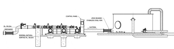
I've attached a section view of the pump station, my thoughts is that it needs an inspections to wear ect but I've been told that its always happenened (even other pump i.e. 1 or 3 were doing the same).

Picture1_sfqczn.png
 
Replies continue below

Recommended for you

One easy test is to see what pressure each pump puts out when you dead head it, I.e close the discharge valve.

If pump 2 is lower than the others then it's pointing to a pump issue.

If not then it's not clear to me why pump 2 would act any differently.

Remember - More details = better answers
Also: If you get a response it's polite to respond to it.
 
Yours is the most common error made by pump specifiers. At dead head you're only looking at pump performance. At all other flow rates, the system has substantial impacts on system performance, especially when operating towards the right side of the pump curve. I suspect s combination of undersized suction header and poor arrangement is creating some pressure dynamics that result in low pressure at the inlet of #2 and hence the poor performance. A suction pressure and motor speed measurement are the next steps to be taken. High suction pressure, high motor speed (closer to synchronous), and low discharge pressure are all indicative of mechanical damage to the impeller or cavitation. The cavitation should be audible.
 
What's the pump suction size?

And is there a separate meter in each pump or how are you determining the flow rate?

Remember - More details = better answers
Also: If you get a response it's polite to respond to it.
 
Hi,

To answer your questions.

Suction manifold is 300mm
Pipe suction offtakes are 125mm (same as pump inlet)
Flows are measured via magnetic flowmeter (one for each pump)
 
Well also when two or three pumps are running try controlling flow on pump 2 to crest a pump curve in situ and see if its different to the one you posted.

It has to be said that those stab in branch connections are fairly "brutal" compared to a swept tee connection.

Maybe the second branch connection wasn't profiled?

Do you have any drawings of the inlet pipe connection?

Those inlet connection look very small. At 40l/sec you're at >3m/sec. That's high for a inlet line to a pump.


Remember - More details = better answers
Also: If you get a response it's polite to respond to it.
 
I agree with the sage wisdom of TugboatEng and LittleInch above:

Tugboat points out that the combination of clues (low suction/discharge pressures, high motor speed) are the "smoking guns" of pump damage.

LI correctly points out that your suction side liquid velocity at >3m/second is way high .... another classic piping newbie mistake.

The correct velocity range for pump suction side velocities is 1 - 2m/sec


As a general rule of thumb, suction pipe velocities should be kept below 2 m/s. At higher velocities, the greater friction causes noise, higher energy costs and increasing erosion, particularly if the fluid contains suspended solids. If your system contains any narrow pipes or other constrictions, bear in mind that the pipe velocity will be a lot higher at these points.

(Please also note the comments in this website about the need for a reducer on the suction piping)

My guess is that there is an flow obstruction on Number 2 pump suction and/or impeller damage. Perhaps you could get access to a boroscope and perform an inspection of the suction piping.

All of this shows the advantages of installing a few test branches (for temporary test pressure gauges) on the pump suction side of multi-pump facilities. (However, you cannot never convince Engineering MBA butt-wipes of the advantages for this logic)


Please provide pictures of your pumping facilities and suction/discharge manifoldss

Keep up posted on your final solution

Regards

MJCronin
Sr. Process Engineer
 
I have seen this happen with large cooling water pumps at a power plant.
Similar lay out just an order magnitude larger in size.
And their inlet side velocities were about 4-5ft/sec.
The could run any 2 pumps of the three and all worked fine.
But if all three were running #2 was inlet starved. You could see it by running P1 and P2, and then turning on P3. The flow through P2 would drop.
They ended up replacing the main manifold. The new one had flow entering across from P2, and both ends fed via long radius ells. That worked fine. It was a lot of large diameter pipe work, but a lot less costly than destroying a big pump.

= = = = = = = = = = = = = = = = = = = =
P.E. Metallurgy, consulting work welcomed
 
Looks like no one is interested in this thread anymore .....

Oh, well ... looks like you will have to put up with the ramblings of a heavily medicated retires old man.

In My Humble Opinion:

First, you suffer from a poor equipment layout. These large pumps should be put at a lower elevation relative to the tank discharge nozzle. I would have depressed the pump inlet centerlines 6 - 10 feet below grade to ensure positive pressure and meeting the NPSHr

Second, your so-called suction side "manifold pipe" is too small at 300mm. Velocities are too high for three pump flow (120l/second) The correct choice would be a 400mm manifold pipe or larger

Third, Your suction piping is too small and should be larger. This is the primary but not only source of your problem. This is compounded by a rough "stab-in tee" connection at the manifold which affects the flow (a weld-o-let or similar contoured fitting is the correct choice) Since you refuse to post pictures or give any other information, this is hard to evaluate

Fourth, your discharge piping configuration is a mess
....NEVER, NEVER, NEVER put an elbow directly on the pump discharge flange.

Well, you saved a lot of money by hiring that nineteen year old, 3D CAD designer for this system...... Take some of that saved money and fix the system.


MJCronin
Sr. Process Engineer
 
Sorry mate, while I’m sure grandstanding makes you feel important you’re way off the mark haha… it’s actually the weekend at the moment so can’t give you any more updates. I have previously mentioned what my plan on the site is.

Just for clarification (it seems you think this is a new installation?). This pump station has been on operations since 1992 with a few upgrades along the way. It’s inlet flow rate has only required the third pump operation in the last 12-18 months.

The pipe sizing choice as mentioned is that based on anything in particular or just rule of thumb (not standard piping sizes where I live - I’d be inclined to use 450 & 250). When I calculate the Npsh it has heaps available. And if my understanding is correct the requirement is greater when it’s only two pumps in operation (when I don’t see as big as a drop off in performance). The losses on the auction side are the valve and tee, losses in the pipeline are negligible from what I can see.

I’ll be happy to take a couple of photos of the installation. next week when I’m back at work…
 
Your understanding is most likely incorrect. Pumps require more NPSHA as flow increases, something like this shows here,
NPSH_pump_test.jpg


Plus the increased flow from the three pumps will reduce the NPSHA in your suction line even more than when only two pumps are operating. That is what most of us expect is leading to the problem.

Whether the losses from the valve, tee and pipeline, even though possibly small, may not be negligible, especially so if you have otherwise unexplained issues such as yours. You really need to get a pressure gage on the suction of #2 before you can say that with any degree of confidence.

I dont need pictures. The drawings are bad enough with the configuration already shown. Pictures would just confirm that. I'd much rather see the suction pressure readings. So do that and listen for pebbles hitting the pipe instead. There is most likely a much larger pressure drop and consequently far lower suction pressure with three pumps running, being that is nearly a 50% flow increase over two pumps running, which tends to greatly lower suction pressure. Friction from increased flow is 1.5^2 > 2x the drop when 2 pumps are running, so you are not out of the woods yet on that issue.

Ignore MJC's attitude, but do not ignore his advice. That's the best you will probably ever get.
 
I understand the decrease in NPSHa when three pumps are running - however wont this also decrease the NPSHr as the pump will move back on curve (lower flow)?? Two pumps are operating at 49L/s, when three run its 40L/s (except the problem pump which is running at 30L/s).

at 40L/s the pump has an NPSHr of 3.31m, when i run the numbers its got at least double it, I do agree though, the confirmation will be the pressure guages and the on site readings.

I guess my point being here is that in two pump operation doesnt see the performance disparity compared to when the three pumps are in operation.
 
No, as it is likely being caused by NPSHA issues, it won't go away. That's the pumps response to being starved of water.

If it was speed controlled and you reduced rpm, yes the reduced flow would require less NPSHA, because you would be feeding it exactly what the reduced rpm wznts. however here you have a pump that wants to run full speed, and takes big bites all the time, but it's not getting a full spoon load. Reduced pressure is the result.

 
Agree with 1503-44 100% !!!.... The effects of my cancer meds are wearing off so I am slowly becoming more polite

Sometimes when you post with a little attitude and humor you can attract more attention, get more detail and enrich everyone's experience !!

....or not !

Lastly, I still suspect some kind of flow obstruction lodged in the suction line for pump #2

Regards to all !!!

MJCronin
Sr. Process Engineer
 
Why is everyone hung up on NPSHA / R. the head loss thru' this short suction line is minimal plus there is a suction tank at atmospheric pressure, without calculating anything, NPSHa is more than sufficient, enrty from the suction line to the pump is unknown but unlikely to exceed the available NPSHa.
Pressure gauge on each inlet, pressure gauge in the discharge header, check the flow meter/s for accuracy.
A stab in the dark, flow velocity past pump 2 with 3 in operation, worth a consideration?

It is a capital mistake to theorise before one has data. Insensibly one begins to twist facts to suit theories, instead of theories to suit facts. (Sherlock Holmes - A Scandal in Bohemia.)
 
Has nobody here heard of a standing wave? If the suction header is undersized it's quite possible for it to develop a standing wave with a node centered on the #2 pump piping.
 
A couple of things.

MJC is known for his sometimes errr acerbic comments. Don't get offended, he means well.

Don't confuse NPSHR with cavitation limit. Normally you need 2 to 3 m above NPSHR to make sure, especially at the right hand end of the curve.

There could well be some sort of flow instability which adds issues to the middle pump. Not heard of standing waves, any more information Tug?

Or it could be the pump itself being not as equal as you think.

Mr 44s idea of a good inlet guage able to measure negative pressure is one way to try and figure out this mystery

But basically a system designed for 2 pump operation being used for 3 is just too small.


Remember - More details = better answers
Also: If you get a response it's polite to respond to it.
 
A standing wave is an interesting possibility..

What would be a way to prove it? Could you throttle 1 or 3 slightly and have that break the standing wave?

If it was a standing wave could you do something like insert a rod projecting into the manifold, say, between 2 & 3 and screw up or 'break' the standing wave?

Keith Cress
kcress -
 
Status
Not open for further replies.
Back
Top