Continue to Site

Eng-Tips is the largest engineering community on the Internet

Intelligent Work Forums for Engineering Professionals

  • Congratulations KootK on being selected by the Eng-Tips community for having the most helpful posts in the forums last week. Way to Go!

Third Pump - Significant decrease in flows 8

Status
Not open for further replies.

catplank

Civil/Environmental
May 1, 2020
15
Hello All,

I’m a little stumped the following… any able to offer any insight?

Normal Operating conditions 2x pumps in parallel. Third pump kicks in on level control. When third pump kicks in its flow/current in the middle pump (pump 2) is significantly lower.

Pump 1 & 3 = 40L/s @120A
Pump 2 = 30L/s @100A

If pump 2 is operating under duty conditions it is inline with the other pump (maybe 1-2L/s lower)

I've attached a section view of the pump station, my thoughts is that it needs an inspections to wear ect but I've been told that its always happenened (even other pump i.e. 1 or 3 were doing the same).

Picture1_sfqczn.png
 
Replies continue below

Recommended for you

It looks like there must be a flow restriction that causes too large a pressure drop/too much back pressure.

Is there a schematic of the piping? This would allow better identifying locations for pressure taps.
 
Thanks -

I have added an isometric that shows some extra details

Picture2_q8pgnd.png
 
What is the pump discharge pressure when operating 1-3 and what is the operating pressure of 2 when running the 3 units?

It is a capital mistake to theorise before one has data. Insensibly one begins to twist facts to suit theories, instead of theories to suit facts. (Sherlock Holmes - A Scandal in Bohemia.)
 
catplank,

IMHO....

Although it doesn't answer your question, it looks like you have some extremely bad piping layout practices in the information you have shared.

First, it looks like you have an elbow attached to the discharge flange of all three pumps (short radius elbow ?) Is that true ? For this type of pump. each pump discharge should go straight up and include a check valve and a shutoff valve.


Second, the pump on the far left has its suction connection attached directly to the termination of the header (should have one ot two diameters of piping at the end to smooth the flow).... this will cause suction problems, vibration and reduce pump life. Is this the pump that is giving you problems ? Somehow, you neglect to give pump names or numbers .... Its almost as if an inexperienced civil engineer did the piping/mechanical layout work ...

Third, it seems that the suction piping to each pump is the same size as the pump flange .... a classic and significant newbie error

Fourth, it is not necessary to have the pump discharges intersect the common discharge header at a 45 degree angle .... I do not understand where people get this

Please explain....


MJCronin
Sr. Process Engineer
 
Sorry Team

Ill chase up from pressure measurements.

MJCronin said:
catplank,

IMHO....

Although it doesn't answer your question, it looks like you have some extremely bad piping layout practices in the information you have shared.

First, it looks like you have an elbow attached to the discharge flange of all three pumps (short radius elbow ?) Is that true ? For this type of pump. each pump discharge should go straight up and include a check valve and a shutoff valve.


Second, the pump on the far left has its suction connection attached directly to the termination of the header (should have one ot two diameters of piping at the end to smooth the flow).... this will cause suction problems, vibration and reduce pump life. Is this the pump that is giving you problems ? Somehow, you neglect to give pump names or numbers .... Its almost as if an inexperienced civil engineer did the piping/mechanical layout work ...

Third, it seems that the suction piping to each pump is the same size as the pump flange .... a classic and significant newbie error

Fourth, it is not necessary to have the pump discharges intersect the common discharge header at a 45 degree angle .... I do not understand where people get this

Please explain....

The pumps are labelled as 1, 2 & 3 from right to left.
Yes there is a Short radius bend, the check valve and shutoff valve are located after the bend.
Pump 2 is the problem child - and only when all three pumps are operating. When operating as a pair (with either 1 or 3) its within 1L/s of the other pump.

Do you have idea why we would only see an issue with pump 2, and only when all the three pumps operate?

Thanks for the comments, appreciate the advice.
 
As always, can you provide pump curves? If the pump is operating in a steep part of the curve there can be significant performance changes with small condition changes.

Otherwise, cavitation causes substantial loss of performance once it begins. A measurement of suction pressure would be my first check. Have you listened to the pumps for the sound of cavitation?
 
TugboatEng said:
As always, can you provide pump curves? If the pump is operating in a steep part of the curve there can be significant performance changes with small condition changes.

Otherwise, cavitation causes substantial loss of performance once it begins. A measurement of suction pressure would be my first check. Have you listened to the pumps for the sound of cavitation?

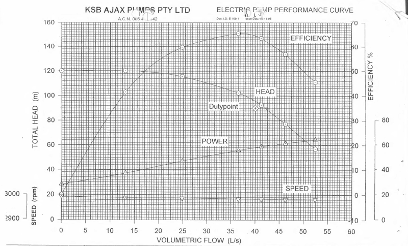
We had used a pressure gauge but it was showing the same across the site (from a suction perspective) it was a large range so i have requested a smaller gauge range so we can see if there is minor differences. Curve Below

picture3_mtdz5p.png
 
You are on the right side of the curve where performance is rapidly dropping off and the NPSHr requirements will be high. Your curve does omit NPSHr which is odd.
 
Certainly an unusual performance and can not see anything obvious, however is it possible with 3 pumps in operation the inlet to pump 2 is being impacted in some way - but why?

A suction gauge on each inlet might flag something - a pressure reading for the discharge head would also help.
It is a capital mistake to theorise before one has data. Insensibly one begins to twist facts to suit theories, instead of theories to suit facts. (Sherlock Holmes - A Scandal in Bohemia.)
 
Agree with Tugboat: ...."Your curve does omit NPSHr which is odd"/...?????

Your piping "isometric" and layout details should be preserved and used in technical colleges as the prime example of how NOT to design piping systems.

Based on a a rough eyeball of your system layout and function, I believe that you have a marginal suction piping layout that becomes a real problem only when the third pump goes into operation

I believe that you should do the following AT THE TEMPRATURE OF PUMPAGE !!!!

1) Get the NPSHr requirements from the pump vendor for the correct pumps and for liquids pumped

2) Perform a detailed NPSH calculation of the system with one, two and three pumps operating

3) Install a cheap (but accurate) pressure gauge on the shared suction header and try to record pump suction piping pressures AS YOU OPERATE WITH DIFFERENT NUMBERS OF PUMPS Use the gauge only for testing and remove it at other times.

4) Evaluate the system 3-pump operation with both a full and nearly empty tank. Does the problem become much worse with a nearly empty tank ? If the answer is yes, then you most certainly have NPSHa problems

Finally, Mechanical Engineers should not design roads, bridges, highways and drainage systems ....... and civil engineers should stay away from process piping systems

IMHO

MJCronin
Sr. Process Engineer
 
If you put pressure gages on the inlet side very close to each pump I believe that you will see pump 2 being inlet starved when all 3 pumps are running.
Your suction piping as very low head and right angle takeoffs, a recipe for flow issues.

= = = = = = = = = = = = = = = = = = = =
P.E. Metallurgy, consulting work welcomed
 
What is the flow when only two pumps are working?

I suspect your pump 2 is simply not as equal to the others as you think.

Supposedly identical pumps can vary quite a bit.

Check the total developed head when running one pump, two pumps with pump 2 and then three pumps and get back to us.


Remember - More details = better answers
Also: If you get a response it's polite to respond to it.
 
Can anyone direct me to some good resources on smart pipe layouts etc for pump stations? I'd be keen to read up and understand some of the more specific things mentioned in the thread so far?

Ill take on board the comments and run some in depth testing measuring suction pressure, discharge pressure and flows.

Ill see if i can chase up the NPSH requirements as well.
 
op talked about 3-pump operation. I just want to double check on 2-pump operation:
How well are loads shared when pump 2 is running during 2-pump operation? (maybe it's just be the weakest pump.. becomes more noticeable as you push it closer to its own lower shutoff head)
Or for that matter is their any comparison of pump 2 alone vs another pump alone.


=====================================
(2B)+(2B)' ?
 
25% variation in performance is rather large to put into a "normal variation between pumps" category. They should be more equal than that. 5% yes, 10% possibly, 20% not likely, 25%+ somethings wrong.

 
Slightly smaller impellor?

We have no idea what the system curve looks like.

Remember - More details = better answers
Also: If you get a response it's polite to respond to it.
 
LittleInch said:
Slightly smaller impellor?

We have no idea what the system curve looks like.

Not sure how the system curve would help? The Three pumps are the same - From the small amount of testing i have seen it is not pump related, rather position related. Running the numbers for the NPSH - (3.3m is the required) there is more than enough avaiable ect.

When Pump 2 and either 1 or 3 is operating it is performing at the duty of when 1 & 3 operate (49L/s). There is only a drop in performance when all three pumps operate (25% in relation to 1 & 3).

I am planning on running each different running combination with a set level in the tank. Measuring suction, discharge, flow.

Ill report back when i complete the testing.
 
Seems to me if 1/2, 2/3, 1/3 are ok but 1,2,3 result in 2 under performing, I would repeat my earlier comment - possibly inlet conditions at 2 is the problem - why????
for interest what is the suction header dia.?

It is a capital mistake to theorise before one has data. Insensibly one begins to twist facts to suit theories, instead of theories to suit facts. (Sherlock Holmes - A Scandal in Bohemia.)
 
Status
Not open for further replies.

Part and Inventory Search

Sponsor