Eng-Tips is the largest engineering community on the Internet

Intelligent Work Forums for Engineering Professionals

Three Link Force Calc 2

eng-wannabe

Mechanical
Oct 23, 2024
2
0
0
US
Visit site
The question in a nutshell: A torque is applied to Link A, what is the resultant torque to Link B?
Here is a simplified diagram:
2024-10-23_07-35-19_zcfs9i.png


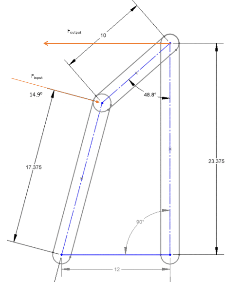
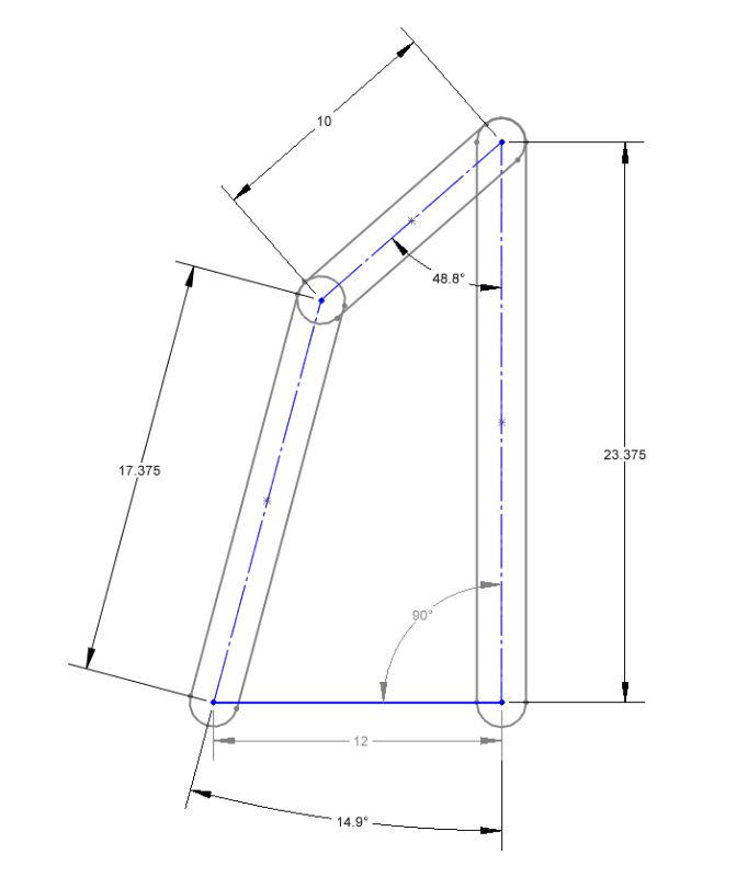
Here is the geometry:
2024-10-23_07-38-01_inxv6e.png


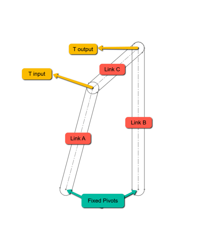
Basically, I have a system wherein a link arm (Link A) is attached to a gearbox, that link arm is attached to a short link (Link C) that is then attached to a third link (Link B), or the object that I am seeking to rotate. For a given input torque (to Link A) I would like to calculate the resultant torque to Link B in various positions, the position being shown is the starting position, Link B will be rotated CCW in 10° increments until it rests in the 9:00 position.

I have contextualized the torque as perpendicular vectors that converge in space, the geometry of which is used to create an output percentage. The torque geo being:
2024-10-23_07-58-15_orbcol.png


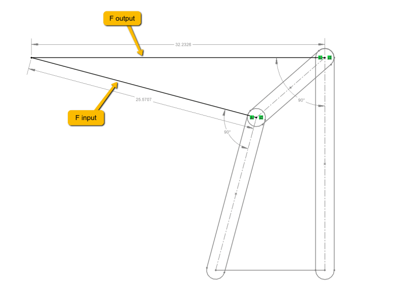
The output percentage being: 1.26 or 126%

My question to the group is: does this track? Is there a better way to calculate this?
 
Replies continue below

Recommended for you

Hi,

Never depart from your basics. Make a free body diagram for each of the 3 links. Once you algebraically determine the X-Y forces acting at point B-C, then the portion normal to the link B axis can be used to calculate your torque. Your algebra will need to be done in terms of the linkage angles, which can change.


Best regards,
Doug Hunter
Altarium Technical Consulting
 
I think, rather than a FBD, you need to do a kinematic model. The bottom two points are fixed, the upper two points move.

You may need to static equilibrium of different positions, but then these are static equilibrium views of a non-static structure (so there is some energy in the rotating members, possibly small.

It's years (decades !) since I did a mechanism but I picture that you need to consider the stiffness of the output (and input ?). If you apply your input load, I picture that there can be an equilibrium set of reacts. Possibly not, if the links are two force members ... maybe look into force polygons, with the links at different angles. Though I'm not sure that'll give you a definitive answer ... it may only give you a direction ? But then scale based on the input load ??

"Wir hoffen, dass dieses Mal alles gut gehen wird!"
General Paulus, Nov 1942, outside Stalingrad after the launch of Operation Uranus.
 
I like the energy method for such analysis. F-input generates a torque through an angle which is work. F-output should generate work of equal magnitude.

T-input * delta-theta-input = T-output * delta-theta-output.

T-output = T-input * delta-theta-input/delta-theta-output

If one has a CAD model, then the ratio of theta-input/theta-output can be generated by making a small change to theta-input and measuring the change in theta-output.

What software was used to make that diagram?
 
This one is pretty easy since the one link is vertical. F output is simply the x component of the F input. You can then calculate the resulting torques. But it seems that torque is irrelevant to your problem.
 
is there not an x component in the LH reaction ?

"Wir hoffen, dass dieses Mal alles gut gehen wird!"
General Paulus, Nov 1942, outside Stalingrad after the launch of Operation Uranus.
 
@3DDave - The software is Solidworks. The term "delta-theta" is foreign to me, what is it's meaning? A google search brings me to a sorority.

To clarify, I am looking for the efficiency loss through this system. Basically, if the torque generated about the fixed point of Link A is 100, what is the torque generated about the fix point of Link B? It's possible that I have over complicated this and it's simply a ratio between the lever lengths, therefore:

Link A / Link B * 100 = F out

Or

134.53

That is not a statement, but a question.
 
"delta_theta" means a change change in theta ... rotate the links to a slightly different angle (like change the 90deg at the RH support to 80 degrees ... how does the other two link move ?)
summing torque about the point of intersection (good idea) you get RL*25.5707(?) = RR*32.2326.
for static equilibrium. you also have ...
sumFy ... Fin*sin(alpha) = RR-RL*cos (theta) ... theta and alpha are obvious angles (?)
sumFx ... Fout-Fin*cos(alpha) = RL*sin(theta)

but I suspect that this structure is not solveable, not in static equilibrium, that it needs a diagonal link to be stable. Fin and Fout must be in a specific ratio else it falls over.

"Wir hoffen, dass dieses Mal alles gut gehen wird!"
General Paulus, Nov 1942, outside Stalingrad after the launch of Operation Uranus.
 
Assuming this is a static case, there will be equilibrium of torques.

So, Torque=17.375F[sub]input[/sub]=23.375F[sub]output[/sub]

So the force ratio is F[sub]output[/sub]=17.375/23.375F[sub]input[/sub]=0.7433F[sub]input[/sub].

But if it is a dynamic case, the inertia forces and moments need to be considered also.

Engineers, think what we have done to the environment !
 
"Torque=17.375*Finput=23.375*Foutput" ... I don't think you can say this, as you're taking torque about different points (Fout about the RH support, Fin about the LH support).

I think you should sum torque about a point, like the RH support, so Fout*23.375 = Fin*(<17.375)+RL*(<12).

"Wir hoffen, dass dieses Mal alles gut gehen wird!"
General Paulus, Nov 1942, outside Stalingrad after the launch of Operation Uranus.
 
Yes, there is a confusion about the point of rotation.

Instead we consider moments about the bottom horizontal line.
moment3_vsnsgm.png

For static equilibrium,

F[sub]input[/sub]cos(17.9[sup]0[/sup])*17.375 cos(17.9[sup]0[/sup])=F[sub]output[/sub]*23.375

Or
F[sub]output[/sub]/F[sub]input[/sub]=0.6942

Or

F[sub]input[/sub]/F[sub]output[/sub]=1.441

Hope I have applied my college funda correctly now.

Engineers, think what we have done to the environment !
 
no, we consider moments about a point. Torque here is Mz. Torque about the RH support includes the LH reaction.

But I don't think we can solve the structure with equations of equilibrium, because it is a mechanism (because it lacks the diagonal member). If we try to build a force polygon with the 5 directions (the three links + the two forces) there is no single solution.

"Wir hoffen, dass dieses Mal alles gut gehen wird!"
General Paulus, Nov 1942, outside Stalingrad after the launch of Operation Uranus.
 
that is a great link for solving this problem

"Wir hoffen, dass dieses Mal alles gut gehen wird!"
General Paulus, Nov 1942, outside Stalingrad after the launch of Operation Uranus.
 
It's a 4-bar linkage.

The "ground" is the fourth bar.

Using the correct name in Google searches like "four bar linkage simulator" or "four bar linkage equations" will get you plenty of useful resources.

 
Hi rb1957

Thanks for your positive comment.

I had a go at solving the posters problem by finding the parallel force in the two bar link and then just using that force to obtain the torque about the longest link.
My estimate for percentage torque output was around 1.28 so very similar to the OP's answer.

“Do not worry about your problems with mathematics, I assure you mine are far greater.” Albert Einstein
 
being snarky (!!??) I'm surprised the answer is not negative. The OP has shown both Fin and Fout positive in the same direction.

I can see that the problem can be expressed as three unknowns (RL, RR, and Fout/Fin) and three equations of equilibrium so statically solvable,
and by solving this we can determine the loads in the links.

"Wir hoffen, dass dieses Mal alles gut gehen wird!"
General Paulus, Nov 1942, outside Stalingrad after the launch of Operation Uranus.
 
Hi rb1957

I did it graphically, I assumed a torque on link(A) and knowing that the force in link(C) has to be parallel to the link I calculated the force on link(C) at the intersection of the links (A)& (C). Now the force at both ends of link (C) must be opposite and equal and so from that force and its direction it’s fairly straightforward to calculate the torque on link (B).

“Do not worry about your problems with mathematics, I assure you mine are far greater.” Albert Einstein
 
and I suspect you changed the positive sign convention of one of Fin or Fout ... forget it, just being a dick ... ask Frank Burns said "I didn't come here to be liked", reply "you came to the right place".

"Wir hoffen, dass dieses Mal alles gut gehen wird!"
General Paulus, Nov 1942, outside Stalingrad after the launch of Operation Uranus.
 
Back
Top