Eng-Tips is the largest engineering community on the Internet

Intelligent Work Forums for Engineering Professionals

Timber Pile Splice 2

Status
Not open for further replies.

jerseyshore

Structural
May 14, 2015
702
0
16
US
Within the last 6-12 months there has been a rush of "lifted house lifts" at the Jersey Shore. Typical house lifts are still happening at a normal pace, but because of the amount of water issues the barrier islands have now, houses that were already up 8'+ are now being raised an additional 1-3 ft. During these lifts the grade of the entire lot is getting raised up by the same amount to prevent the everyday rain/ bay water from flooding the ground floors.

Now this is typically done by cutting down the existing timber piles, installing a grade beam foundation, then building CMU/ concrete piers back up.

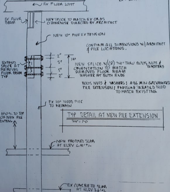
However, and as you can see in this picture below from a friend, engineers are signing off on timber pile splices like this now. How they justify this I have no idea and it's not something I have ever considered honestly. Seems like a waste of time to perform an analysis/ design just to find out it won't work anyway.

Most timber pile splice details I have seen are usually from DOT manuals for bridges and things of that nature.

Has anyone successfully detailed a timber pile splice like this and got it to work out on paper?

Re_pile_cflog5.jpg


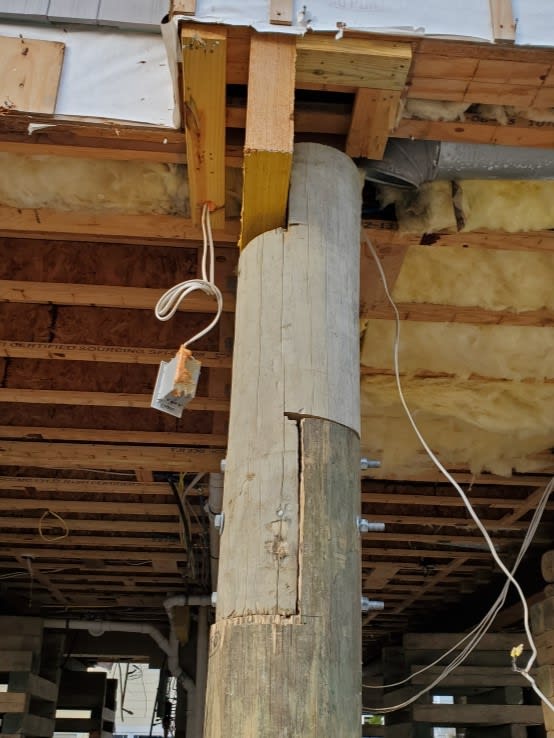
(I love the overcuts from the circle saw on the splice piece, it adds a real nice touch of craftsmanship to the entire thing)
 
Replies continue below

Recommended for you

That is heinous.
I've never tried to calc that but it wouldn't meet the calcs anyway thanks to the crappy work on that one...

With timber piles (below ground) they sometimes break or aren't long enough so the pile manufacturers have steel helmets that they put on top
Something along that line could work but is pretty ugly, and only really works for gravity loads
Not great for any kind of lateral load
 
I don't have anything useful to add, but wow! Does construction of that type have to get permitted or inspected? I don't live anywhere near timber pile foundations like that in the land of deep frost...
 
Normally this would not pass most of the NJ shore inspectors, but my friend just sent me the detail sheet from the engineer and it matches this exactly. I couldn't believe someone signed off on it either. What I was told was that this was detailed by an engineer months ago so the town approved it last week for construction. Wild stuff. Total splice height was about 34 inches.
 
Honestly, it will probably work fine. I would not sign off on it though. I'd love to see some calcs. Maybe query the engineer who produced the detail as a "professional courtesy"
Even if the splice manages to not fail, will the longer pile still perform as intended?
 
If you can justify that it is an axial member only, not part of the LFRS and no wave/flood loads are induced on the upper portion of the splice - than it could work. There is still the eccentricity to deal with but that may actually work out by the numbers.
 
Looks like a reasonable detail to me - am I missing something? End distance for the bolt is always a concern. As I recall it needs to be 7 times the bolt diameter.

DaveAtkins
 
We haven't been in a situation that justified splicing a timber pile. We always recommend full replacement or partial replacement using the methods JerseyShore mentioned.

Besides the obvious reduction in bending capacity, the detail can be problematic if the cuts aren't carefully made. If there is a gap in the horizontal surfaces, you may end up applying the axial load to the bolts instead of transferring the load to the timber. There's also the potential issue of exposing the piles' un(der)treated centers to water and rot. I'm also concerned if the carpenter doesn't undersize the bolt holes so there's a tight fit.

I've seen fiber-reinforced composite splices, but they seem more of a headache than they are worth.
 
I'm sure this is done more frequently than I've seen, but I just don't know how you get those 3 bolts to work for high wind loads with a 2.5 story house above. Even if you have 6 or so piles in a row.

Typically on these houses there are no pile designs for lateral, just a tonnage for bearing capacity. But any time I've ran numbers on beam to pile connections that stray outside of the typical 2 bolt setup, it's not always easy to prove on paper.

And MTN is correct about quality of construction. The roughest cuts and craftsmanship I see in residential work is at the top of these piles. Overcuts, uneven cuts, oversized holes, non-treated cut ends, etc. are all happening on nearly every job.

 
jerseyshore said:
I just don't know how you get those 3 bolts to work for high wind loads with a 2.5 story house above
I was curious about this, so I ran some numbers for the scenario where there's a lateral force acting in the plane of the splice. In this case, the lateral capacity of the bolts is resisting the full moment at the splice (plus the shear force).

Since NDS doesn't exactly address this type of connection with round timbers, I'll assume the piles are instead 8x8 square sections, with the splices being 4x8s. (I doubt this would make much of a difference). From Table 12A, assuming the piles are Doug Fir or similar specific gravity, I get Zperp = 430 lbs for two 3.5" members connected with a single 1/2" bolt. Assuming the loading is wind/seismic, CD = 1.6. Based on the picture, I'm assuming the total splice length is 12", with the bolts about 2" from the end of the pieces, and 4" between bolts. With the end distance only being 2", it's very close to the lower limit of 3.5D which corresponds with Cdelta = 0.5. I'll just use that value for simplicity since I'm guessing the real distance anyway.

Assuming all other adjustment factors are 1.0, I get a single bolt lateral capacity of:
Z' = Zperp x CD x Cdelta = 430 x 1.6 x 0.5 = 344 lbs. The bolt capacity is clearly garbage. (I often forget just how bad single shear bolted connections are with perp. to grain bearing.)

At this point it's not really necessary to carry out further calculations, but I was also curious what magnitude of loads the bolts might be subjected to in this splice. I'll admit that I've never designed a wood moment connection like this and the analysis took an embarrassing amount of time and may yet be incorrect. With that said, assuming the worst case scenario of the splice being 3 ft long (house being raised 3 ft), using the splice dimensions noted above, and choosing an arbitrary lateral load, P, of 1,000 lbs applied at the floor level, I calculate lateral loads acting on the three bolts (top to bottom) of 5,600 lbs, 300 lbs, and -4,900 lbs. (The negative sign indicates the reaction is acting in the same direction as the load P, as necessary to resist the moment.)

So, clearly a 1,000 lb lateral load is significantly more than the splice can take. If my analysis is correct, the splice can in fact only resist about 60 lbs laterally.

I would assume these splices are not being used to resist lateral loads. Perhaps there are diagonal braces or an altogether separate lateral system for these structures. In terms of resisting vertical loads only, I don't love this splice, but I wouldn't be as concerned in that case.
 
Eng16080 said:
Assuming all other adjustment factors are 1.0, I get a single bolt lateral capacity of:

You're missing wet service factor here, I think it reasonable to at the very least adjust Z' by 0.7 for wet service conditions during installation.
Capture_uuug2x.png
 
ChorasDen said:
You're missing wet service factor here, I think it reasonable to at the very least adjust Z' by 0.7 for wet service conditions during installation.
Fair enough! I wasn't necessarily meaning to check everything, and based on the picture, it at least looks dry.

Depending on how you interpret that table and the range of potential moisture contents at fabrication and in service, it's possible CM = 0.4 might even apply.

Ok, so with CM = 0.7, we're down to a lateral force of 40 lbs.
 
Well here's the engineered detail that I will share. Not that it will make a massive difference in your calculations.

There are no other foundation/ ground floor lateral systems for 95% of these houses in NJ. Their lateral resistance is solely based on the number of piles in each row. For houses that are more rectangular and are only 3 piles wide, those are noticeably racky (is that a word?) in the short direction.

Typically if a house is going to be higher up I'll specify 12" piles. Houses not that high up, 10" piles. Foundation lateral design complete.


Re_pile2_f65pxq.jpg
 
@Eng16080,

The center of the bolt group would be 2'-6" +/-
Assume the middle bolt takes the shear.
So M= 2,500 Z = 2500/1 ft = 2500 lbs
So the bolt loads are 2,500,1000,2500.
Still overstressed significantly but in practice would probably survive.
1,000 lbs shear at the top of the column is probably unrealistically high

edit - looks like the bolts are 10" apart so the numbers are little higher!
 
JerseyShore said:
3 piles wide, those are noticeably racky (is that a word?) in the short direction.
I've been in a few beach houses that I could feel moving side to side from just humans walking around. Looks like they were adding a slab at the bottom which may help with the pile's moment capacity
Seems like a case where you may want to reach out to that engineer or the board of engineers.
 
Status
Not open for further replies.
Back
Top