Continue to Site

Eng-Tips is the largest engineering community on the Internet

Intelligent Work Forums for Engineering Professionals

  • Congratulations KootK on being selected by the Eng-Tips community for having the most helpful posts in the forums last week. Way to Go!

Tolerancing Slots From an Angled Datum 3

Status
Not open for further replies.

Words_In_Sequence

Mechanical
Feb 20, 2023
4
Hi All,

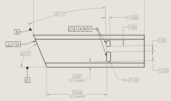
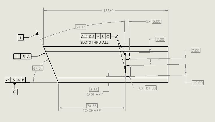
I am working on the part attached. The item is a tube with an angled cut that will be mitered with a mating tube inside of a weldment. The location of the rectangular slots from the angled face (datum B) is important. The slots themselves are angled and act as a locating feature for a tabbed plate (not shown). The slots are to penetrate both walls of the tube (the part is reversible). Because of how these slots are oriented (not parallel or perpendicular with any particular face) I am not sure of the best way to located & tolerance them.

My thought is that because the angle face is what's important they should be located from there. Due to the fact both the datum and slots are not parallel, I have opted to dimension from the corner of the miter to the sharp of the lower slot to set the x-position. Additionally I have defined datum C as the face of the tube angled basically 67.5 degrees from B. I use datum C to set the Y-position of the slot by basically dimensioning to the sharp. To control the overall location of the slots I am using an all around profile of surface on the two slots relative to A|B|C. I have defined the bottom face of the tube as datum A since the slots orientations to that face are important.

My questions are as follows:
1. Is this an appropriate dimensioning scheme for this application (i.e. is this a good way to locate these features or is there a more clear/easier to measure way to achieve the same result)?
2. Does Datum C need to be qualified to datums A or B, or is my current set up acceptable?

This is my first time posting so if any information appears to be missing or clarification is needed please let me know. Thank you!
 
 https://files.engineering.com/getfile.aspx?folder=f479db8d-01a5-4d33-b832-51d0cf2d3eec&file=SLOT_PROFILE_FROM_ANGLED_DATUM.JPG
Replies continue below

Recommended for you

I snipped just the key part; the end view is square tubing with large corner rounds. Datum feature A is the rear face of the tube. This view includes the tangency lines.

slot_lybdwt.png
 
Basic dimensioning from the intersection of datum features B and C should work fine. Your datum selection scheme, by default, will set the origin of the datum reference frame (the coordinate system used for locating and orienting the tolerance zones) at the intersection of datums A, B, C.
You do need to qualify datum feature C relative to A primary, B secondary.

Screenshot_20230221_062053_Drive_lsclgk.jpg

Screenshot_20230221_062243_Drive_idhrvk.jpg
 
Since datum feature C appears to be a stock material face, I expect things will not go fine, but I don't want to go into datum targets when there is no clear function for the way it is currently dimensioned and toleranced.
 
It is probably better to use the 40 mm width between faces as datum feature A, instead of that one face.
 
3DDave and Burunduk,

Thank you both for your replies.

Burunduk, what would be the purpose/benefit of utilizing the width feature as datum A as opposed to the one face?

3DDave, without having you go into too much detail, what is the problem you see with using the stock face as datum C?

I have attached the newest iteration of the drawing based on the feed back provided thus far.

SLOT_PROFILE_FROM_ANGLED_DATUM_-_R2_wjxbxx.jpg
 
Also looks like a good application for dual tolerance, one to control shape at a tight tolerance relative to A or A|B, and a looser tolerance for location A|B|C.
 
Words In Sequence,
The slots pass through both faces.
If you select one face as the primary datum feature, it means you directly control how perpendicular both through slots are to that one face, but you have much less control over the relationship of the slots to the other face. If both faces are equally important (which makes sense because the slots are through both), you may want to make a center plane datum out of them. With that said, the faces need to be adequately parallel to avoid an unstable primary datum feature. The tolerances that control the faces which may define the stock part could be a useful indication.
 
Words_In_Sequence,

Your part would be way easier to fixture if the angled face were your tertiary datum feature, instead of secondary. I take it this is commercial off the shelf tubing?

Is this really a good description of your requirement?

--
JHG
 
Since there is no description of how this part is to interact with other parts, suggestions are incomplete guesses.

It's also a question of how the raw stock tolerances measure up against the control applied to the surface used as datum feature C.
 
TheTick_gosamr.jpg


That is an interesting point. Since they slots are oversized features to help locate a tab in a weldment I am not sure the tighter orientation requirement is necessary.

Burunduk_dbe5vc.jpg


That makes sense. Thank you!

drawoh_ufsn0v.jpg


Regarding making it easier to fixture, why would this be the case? In regards to my requirement, see the image at the bottom of this post.

3DDave_ughsko.jpg


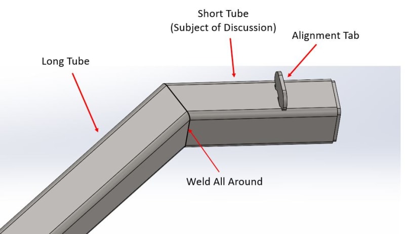
Perhaps an image showing the application is warranted. Please see below. The tube will be welded to the face of longer tube. The weldment is used inside of an assembly for a cart. The tabs welded to the short tube are used to line up the cart with the object it will carry.

Weldment_Annotation_ajwoug.jpg
 
Words_In_Sequence,

So what you really need is to locate that alignment tab.

Don't tell your welder how to do his job. Tell him where the alignment tab must go, and let him figure out the fabrication and fixturing.

--
JHG
 
I recognize a previously encountered trap in this design.

The trap is when there is a demand that no parts can ever go back to the machine shop and all parts will be machined, then welded, and then painted, in that order and only that order. What makes it even better is the demand that no money is to be spent on any weld fixtures as that cost has not been added to the budget.

The result of these rules is sloppy and craptacular. It might work, but it often looks questionable with parts fitting awkwardly or needing a grinder at final assembly to install.

The better approach is to weld in some substantial tabs with reasonable controls on the finished tube locations/orientations and allow for enough material for machining the tabs to meet the variation limits the design requires.

The best approach is to avoid the need for small precision items on weldments, but there's not enough information here to determine how that would be accomplished.

 
Thank you both for the feedback, I have removed the slots from the small tube and switched to controlling the tab at the weldment level so that the weld team has more freedom to determine appropriate fixturing and fab methods to meet the design requirements.
 
Status
Not open for further replies.

Part and Inventory Search

Sponsor