Eng-Tips is the largest engineering community on the Internet

Intelligent Work Forums for Engineering Professionals

topping on precast roof members 2

Status
Not open for further replies.

smvk3

Structural
Mar 1, 2014
57
0
0
US
I'm designing a storm shelter where the gross wind uplift is on the order of 225 psf. We will be utilizing either precast hollowcore planks or double tees as the roof system with a 4" topping to resist in-plane diaphragm forces.

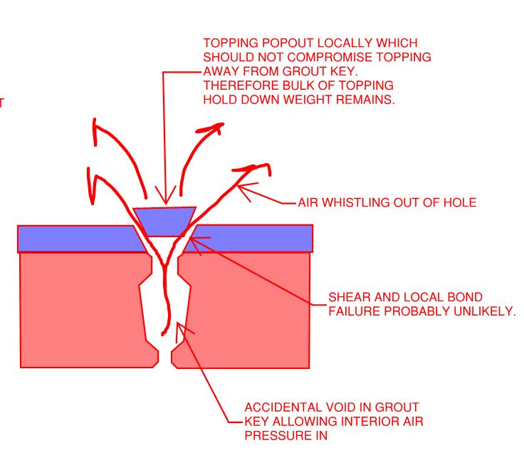
How is the topping slab anchored to the roof members for net uplift loads? By inspection, the 50 psf weight of the topping won't be close to resisting the gross uplift loads so how is it typically anchored to the roof members? I have seen hairpins embedded into the stem of the double tees but I'm not sure if that is for composite action or providing a positive connection between the roof member and topping.
 
Replies continue below

Recommended for you

With double Ts, can you use weld plates and forget the topping? If you need the concrete topping, then inserts to secure the WWM topping reinforcing, else check to see if concrete will bond to DTs sufficiently.

Rather than think climate change and the corona virus as science, think of it as the wrath of God. Feel any better?

-Dik
 
With a properly bonded topping slab, you should have vastly more tensile bond capacity than you need. In canada, the code minimum is 0.9 MPa which is easily achievable.
 
KootK is correct. But the uplift pressure, presumably from a tornado (as that is the only possible natural phenomenon which can approach that magnitude of pressure), is not just applied as suction. The uplift is due to the pressure differential inside and outside the shelter. So as long as there is intimate contact between the topping and substrate, your particular concern is moot. I would be more concerned with the design of the roof members, as well as their tiedown details.
 
hokie66 said:
KootK is correct. But the uplift pressure, presumably from a tornado (as that is the only possible natural phenomenon which can approach that magnitude of pressure), is not just applied as suction. The uplift is due to the pressure differential inside and outside the shelter. So as long as there is intimate contact between the topping and substrate, your particular concern is moot. I would be more concerned with the design of the roof members, as well as their tiedown details.

Something has always bothered me by this line of thinking. Is there not also a pressure differential that occurs as a function of time? The exterior pressure at this location is constant and then as the wind event occurs the pressure quickly changes. Would this not apply a temporary suction until the exterior pressure becomes somewhat constant during the wind event?
 
dik: That is an option but we usually prefer the topping slab to give the precaster the option to design as composite and I like to use the topping as a diaphragm. What is the methodology of using the inserts? Are you assuming the inserts are the support points for the slab by anchoring the topping reinforcement to the inserts? What do the inserts look like?

Hokie: Can you elaborate on how holding down the topping slab would be moot? I see the topping slab at least being required to resist the uplift from suction alone (without the positive internal wind pressure) which would be on the order of 147 psf (gross). Using 60% of the topping slab weight I am getting a net uplift to be resisted by the topping alone of 59 psf (0.6D - 0.6W)?

KootK: Can you elaborate more on the tensile bond capacity? I don't anticipate the contractor providing any type of structural bonding adhesive to the top of the precast members.
 
a matter of anchoring the topping in the event bond is insufficient.

Rather than think climate change and the corona virus as science, think of it as the wrath of God. Feel any better?

-Dik
 
OP said:
KootK: Can you elaborate more on the tensile bond capacity? I don't anticipate the contractor providing any type of structural bonding adhesive to the top of the precast members.

A normal topping applied via normal practices to a TT system with a boomed / roughened top surface should easily achieve 0.9 MPa tensile bond. Normally the topping design is the preview of the EOR but you might attempt to issue a performance specification instead, recognizing that no special bonding measures are likely to be required. For hollow core planks, there is evidence that even the broom finishing not not required to achieve the tensile bond. Rather, the natural roughness of the machine cast plank surfaces themselves are adequate.
 
hokie66 said:
Where did you come up with the 147 psf of suction? That is ludicrous. Do you see rigid pavements blown away in tornados?]

Why wouldn't there be suction at the roof of a 22' tall storm shelter under 250mph, partially enclosed wind loads?
 
smvk3 said:
Why wouldn't there be suction at the roof of a 22' tall storm shelter under 250mph, partially enclosed wind loads?

I believe that what hokie66 is alluding to is the phenomenon by which there sort of is no such thing as "suction" in a steady state wind environment. Rather, the uplift is a product of the pressure differential between the stagnant air in the interior of the building and the fast moving air out side the building. Because the stagnant air cannot get into the space between the topping and its substrate, the uplift affects the topping and its substrate as a unit rather than in isolation.

I think of this as analogous to how there's no buoyant fluid pressure on an object if no fluid is actually able to get beneath that object.

EZBuilding said:
Is there not also a pressure differential that occurs as a function of time?

But then there's that. I don't know the answer to that but would certainly like to hear more about it.
 
I still don't follow the whole concept of "no suction"; there is documented evidence of tornado's (albeit extremely rare, violent ones) that have caused ground scouring and peeling off of road pavements.

Kootk, what's your thoughts on threading the topping reinforcement through embedded hairpins that partially stick out of the precast members to provide a more positive uplift connection between the topping and precast member? I would then design the topping for the uniform net uplift load and treat it like an inverted raft foundation with the hairpin has my support or "columns"
 
smvk3 said:
Kootk, what's your thoughts on threading the topping reinforcement through embedded hairpins that partially stick out of the precast members to provide a more positive uplift connection between the topping and precast member?

I think that would be an unnecessary waste of effort and money. Of course, its not going to hurt anything structurally.
 
Check out this article:Link. Whether or not the dynamic situation with a Tornado is different, I can't say. I always thought that the pavement liftoffs where this mechanism:

1) high speed debris hit the pavement and create gaps allowing air to get beneath the pavement and its substrate.

2) #1 sets up the usual pressure differential between fast and slow moving air.

That, or the air above is moving so fast that it's practically a vacuum and the stagnant air in the interstitial spaces of the sub-base creates enough pressure to generate liftoff.

c02_r1bjyb.jpg
 
Kootk said:
That, or the air above is moving so fast that it's practically a vacuum and the stagnant air in the interstitial spaces of the sub-base creates enough pressure to generate liftoff.

I agree that is probably the main mechanism for what we are calling "suction".
 
KootK said:
But then there's that. I don't know the answer to that but would certainly like to hear more about it.

I started this line of thinking when an old boss of mine told me that a sign attached to the side of a building wouldn't experience any negative wind pressures due to the exact same reasoning. I disagreed, and ASCE 7 had some guidance which agreed with my position. See ASCE 7-16 29.3.2.

ASCE_7-16_29.3.2_hqiuik.jpg


It is interesting that this provision even applies when there is up to a 3 foot gap between the wall and the sign.
 
Is there truly no air pressure on the underside of a precast topping? I suppose this depends on the keyway grouting and how well that forms an airtight seal. It would seem to me that there could be locations where an airtight seal is not achieved, and where the topping could see air pressure from below? May be a moot point considering the magnitude of the bond strength available.
 
Craig_H said:
It would seem to me that there could be locations where an airtight seal is not achieved, and where the topping could see air pressure from below?

I think that's probably right, albeit probably still not a cause for concern per the sketch below.

C01_pftgfa.jpg
 
EZBuilding said:
I disagreed, and ASCE 7 had some guidance which agreed with my position.

Fascinating, thanks for sharing that.

Allow me to posit an alternate interpretation of 29.3.2. Don't interpret this as me claiming to "know" anything on this. It's just me spit balling a little devil's advocacy in search of some insight.

29.3.2 SOLID ATTACHED SIGNS - KOOTK ALTERNATE INTERPRETATION

1) What's it take to have no air pressure behind one of these signs?

a) Sign in general contact with wall? Nope, there would still be plenty of tiny air filled gaps between sign and wall.

b) Airtight seal around the perimeter of the sign? Nope, that would just trap a pocket of stagnant air in the small spaces between the sign in the wall.

So, since it's effectively impossible to not have stagnant air behind the sign, we're going to explicitly tell you that you DO have to design for such and such pressure in these situations just in case folks try to get clever with the whole "there's no air behind" the sign thing. The only out would be to tell folks that their signs have to glued to the wall over the entire contact interface in such a way that no air pockets were left and the seal was airtight. Obviously, that's a whole lot to ask.

2) So what air pressure should be used?

a) Since the air behind the sign is effectively zero velocity and at the stagnation pressure when a gust comes along, let's use the C&C loading with the interior pressure set to nil.

b) Since the air behind a sign will be at stagnation pressure up to 3' separation, let's include those scenarios here too. I have no idea whether or not 3' is the distance at which the stagnation pressure argument is valid. I'm totally speculating with that.

END INTERPRETATION
 
Status
Not open for further replies.
Back
Top