Continue to Site

Eng-Tips is the largest engineering community on the Internet

Intelligent Work Forums for Engineering Professionals

  • Congratulations KootK on being selected by the Eng-Tips community for having the most helpful posts in the forums last week. Way to Go!

Tourist submersible visiting the Titanic is missing Part 2 69

Brian Malone said:
And they had changed hull manufacturer from Spencer Composites to either ElectroImpact or Janicki. Has the manufacturer been determined?

According to Factual Report 24-011, ElectoImpact[sic?] did the winding and Janicki did the curing.
 
The cross-sectional photos showing the fiber waves was not filament wound. You can see that unidirectional prepreg tape was used because the fiber layers are very uniform thickness with no visible tow structure. ElectroImpact makes fiber placement machines, which can use slit tape. But even there you will generally see some variable gapping between slits within the tape layer.

However, thick-walled cylinders are one of the most challenging structures to make from prepregs because prepregs are usually about 5 to 10 percent thicker than the final cured ply thickness. This means that any compaction that occurs during cure will result in wrinkles and waves in the fiber. Compacting a cylinder means reducing its outer diameter, and thus circumference. Carbon fibers are among the stiffest material known. They don't compress anymore than about 1% to failure at max load. Wet filament winding uses low viscosity resins so that full compaction occurs during winding (due to fiber tension), so wrinkling is generally not an issue.
 
The more I see of it the more I become convinced that the hull layers could just as well be slathered with mold release between each step and seen no difference in performance. It appears little better than friction was carrying the shear loads.
 
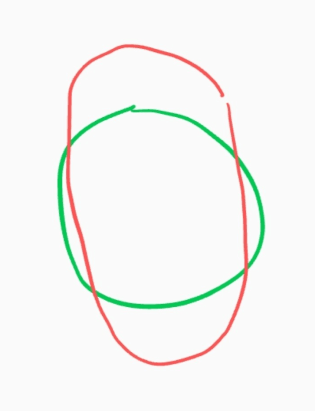
I think I see why the outer flange failed in tension. Notice that it's still attached in two locations roughly 180 degrees apart. The green circle represents the dome and the red oval is the shape of the CF tube as it failed. Sorry for the crude drawing, in the shipyard killing time.

Screenshot_20240927-132233_ko85jy.png
 
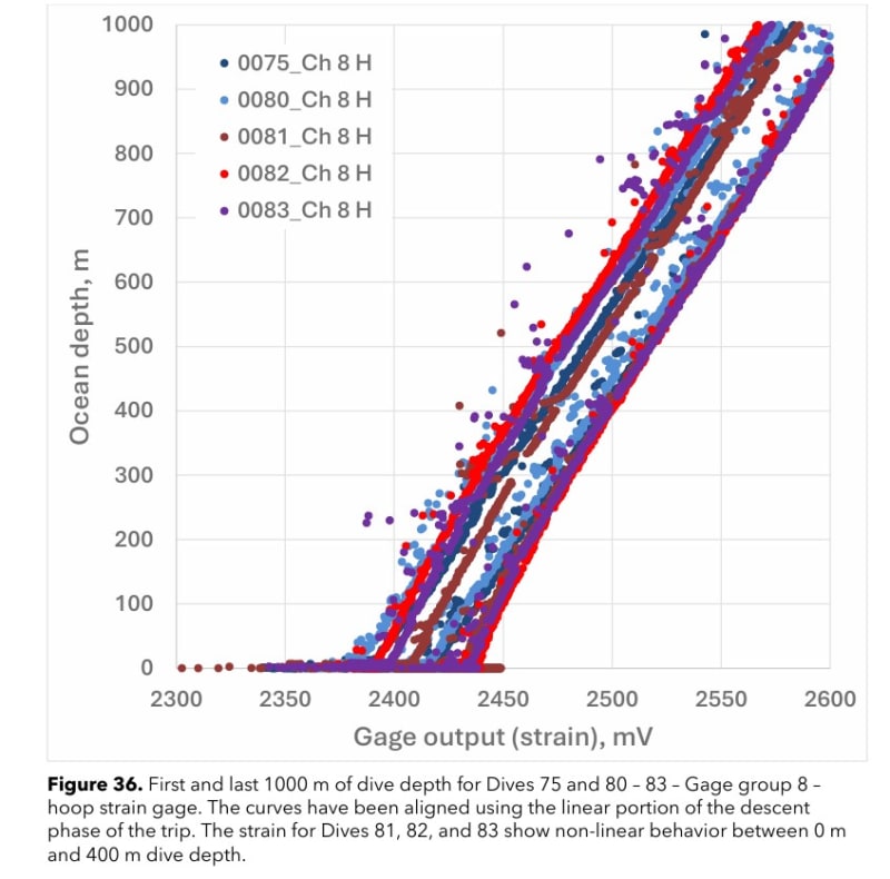
In the shorter report (55 pages) on the ntsb site, this image is presented:
Screenshot_wk7geu.jpg


Further images zoom in closer, but the bottom line: a shift in the strain gage vs. load (load=depth which is analogous to external pressure) occurs on a number of the gages recorded (and still functional) across dive 75. Dives 81 through 83 seem to show a nonlinear "hysteresis loop" in the strain vs. load curve, i.e. the strain response follows a different line depending on whether the craft is ascending versus descending. Which would be a major red flag, you'd think? Except, according to testimony, nobody at OG thought to plot strain vs. depth, nor to overlay the traces...they just plotted strain and depth vs. time over the duration of each dive.

Everywhere you look, you see ignorance, hubris and outright negligence.

edit: oh, and failed strain gages were brushed off, no attempt made to figure out why they were no longer working.
 
Remember that the failure did not occur with the CF tube collapsing in the middle. It seems that Stockton Rush was not incorrect about the factors he spoke about. Instead, there were other factors that doomed the tube. Specifically, in my opinion, this was the bond between the tube and domes.
 
btrueblood Dive 80 exhibits hysteresis so the effect does not appear to have happened exclusively at Dives 81 thru 83. Wouldn't more info (temperature, system electrical stability, etc.) and analysis be required to determine significance of any offset? Does the NTSB report state why the strain response of these last dives is presented?

Edit - Now I see the differing load/unload offset of the Dives 81 thru 83. Dive 80 has offset similar to Dive 75. So possibly Dives 76 thru 79 were not to 1000 meters, thus not included in the analysis?
 
If the tube had the integrity of a wet noodle so all loads were held by local bending at the interface with the rings then the glue joint there would be the sole cause of the failure. OTOH, had the tube remained fully rigid, as the rings appear to be, then no more glue would have been required than was used to hold the domes to the ring.

I think the actual failure is somewhere in between with failure of the tube to retain stiffness due to inter-layer mold release putting unnecessary loads on the glue, much like a weak flooring system allows enough flex to pull away from the edge supports.


---

Dives 81-83 are interesting because the hull response is no longer a straight line at the start of the dive above 300-400 meters (nice of them to use fat dots.)

The hysteresis on all dives is likely because the hull changed temperature during the dive.
 
Brian Malone said:
Edit - Now I see the differing load/unload offset of the Dives 81 thru 83. Dive 80 has offset similar to Dive 75. So possibly Dives 76 thru 79 were not to 1000 meters, thus not included in the analysis?

OG did not restart counts on dives between V1 and V2. Only dives 2000m and below on V2 were 63, 65-70, 73, 75-76, 79-83, and the implosion dive 88.V2 began its diving with dive 50. V2 dives were mostly 200m or less test dives, mostly at depths of 1-10m. Two aborted dives around 1300m and 1700m thanks to thruster failures. v2 made ONE system test to under 2000m before paying passangers were taken to 3840m.


Thruster, drop weight(lots of manual rocking of sub to get weights to fall off), collisions, fires, and sensor failures were plentiful on deep dives, so the data is not great to begin with.


Edited to correct grammar.
 
There is much more evidence against adhesive failure as primary root cause that there is for it at the moment.

None of the adhesive bond line faces documented thus far exhibit the signs of an adhesive failure in shear; all indicate failures in tension.

Tension failure of the adhesive can't be the first point of failure.
 
There are areas where the failure isn't in the adhesive layer but at the bond to either the carbon fiber or the titanium. It's not possible to tell if that is tension or shear.
 
Were any traces of adhesive found on the OD of the outer most layer and ID of the inner? A few of the photos of the recovered wreckage made it look like they did bot have complete coverage of adhesive. I think one photo showed a clean line right up to only about half of the outer layer. V1 had "unsightly" adhesive ground off wherr it squeezed out at the rings to cylinder interface. Rush's mindset of not worrying about the sealing surfaces because the pressure will be keeping the domes and flange squeezed on only makes me wonder if they would have taken steps to prevent adhesive squeezeout when fitting the flanges to the V2 hull.

If there was a lack of adhesive there, I wonder if water slowly worked its way to inbetween layers of the cylinder from the machined end. The sensors with acoustic events were right there near the interface.

Short of gaps allowing water intrusion, how could the adhesive bond fail under pressure and lead to the implosion?
 
If you watch the video of the assembly, the adhesive joint was clearly not properly prepared. The surface was as machined. Metals that form passive layers such as aluminum, stainless steel, and titanium need to be grit blasted immediately before bonding to remove the passive oxide layer.
 
Photos of the rings show that where the adhesive actually made contact with the titanium, it stuck pretty well, whereas there are other areas that are devoid of adhesive, indicating either poor surface prep, or no actual contact with adhesive was made at all.

I'd vote the latter, even though they obviously didn't prep the surfaces well, since they also didn't exactly do a meticulous job of ensuring proper adhesive contact with the entirety of the ring either, given Rush's presumption that everything was in compression, at depth, so one could play loosey-goosey with things like fasteners.

TTFN (ta ta for now)
I can do absolutely anything. I'm an expert! faq731-376 forum1529 Entire Forum list
 
Tug, the video of the ring being set was of V1 hull. As far as I am aware, no video exists of the rings being cleaned of old adhesive and set on the V2 hull.
It wasn't just as machined either. The VTL the rings were machined on is a few feet away in the background. It probably just got some acetone or contact cleaner spray downs right off the chuck before they began to adhere it and was filthier than a mofo.

Some of the marks on the failed adhesive look like old adhesive that was not completely wire wheeled off as well, so there could also have been adhesive to adhesive bonds. I cannot find those images on the uscg site anymore however. They still have the 55 page materials test up, but not the 70+ page; likely down for more redactions.


Edit: Well well.
USCG hearing said:
The trimmed hull was then bonded to the forward and aft segments. The
segments (and domes) were forged and machined from commercially pure (CP)
Grade 3 titanium (UNS R50550). Illustrations of the aft segment are shown in figures 4
and 5. The hull-facing side of both segments contained an annular C-shaped channel
into which the hull was inserted and butt-joined using an epoxy paste adhesive
(Loctite EA 9394 AERO, also known as Hysol EA9394). The segments and domes
were originally used with the first full-scale iteration of the Titan hull. After that hull
was retired, the remnants of the hull were removed from the segments by machining.

According to a former director of engineering and a written OceanGate
process specification, the segments and hull surfaces were prepared for bonding by
degreasing with methyl ethyl ketone (MEK) and roughening with stearate-free
sandpaper. Contact angle measurements were taken between steps to ensure active
(i.e., non-contaminated) surfaces and particulates were blown away using filtered
shop air (tested by contact angle to ensure it did not introduce contamination). The
adhesive was mixed and applied to both the segment and hull bonding surfaces. The
hull was then inserted into the C-channel. The aft joint was formed by lowering the
hull down onto the segment and the forward joint was formed by lowering the
segment down onto the hull, the entire assembly oriented vertically. Spacers within
the joint controlled the bond line thickness.
Most of the adhesive originally used to bond the hull to the titanium segment
had disbonded from the machined end of the hull piece, but there was an
approximately 3.5-inch-long patch where some adhesive bits were still attached,
shown in figures 25a and b. Most of the patch was between 0.030 inch and 0.034 inch
thick. In a smaller region, the adhesive measured between 0.055 inch and 0.064 inch
thick, all measurements performed by caliper. As previously described, the process
for bonding the hull to the segments involved applying excess epoxy adhesive to
both the end of the carbon fiber hull and the flat face of the titanium segment’s Cchannel. The appearance and thickness of the thinner adhesive region was consistent
with a separation at the interface between the adhesive applied to the hull and the
adhesive applied the titanium. The appearance of the thicker patch was consistent
with a separation at the interface between the adhesive and the titanium.
 
From the NTSB reports in the NTSB docket files, Chair's Factual Report 24-012:

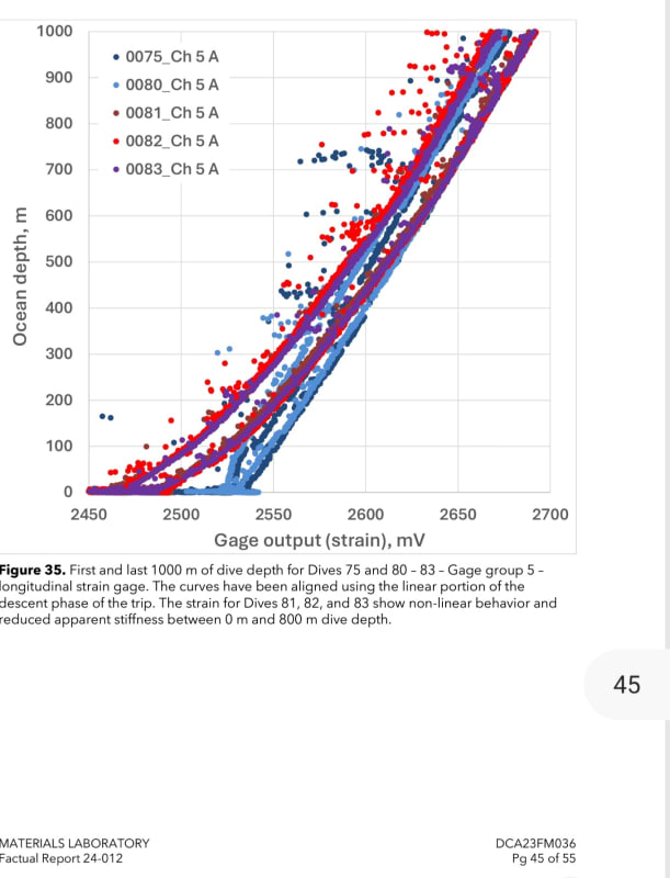
NTSB exhibits an apparent change in stiffness of the hull in their Fig. 35

Screenshot_20240930-004304_Adobe_Acrobat_zepeox.jpg


I believe the 5A sensor group was on an axial line at the mid point of the hull. Refer to page 8 of the sensor layout shown in 'CG-058 Titan AE and Strain Sensor Locations_Redacted:
 
In the CG files there is the early structural analysis by Spenser Composites for the first hull. It has some FEA for the hull but appears not to analyze the titanium interface rings in detail. Has any interface ring analysis been presented?

Edit - missed the image on page 5 in the CG-058 Titan AE and Strain Sensor Locations_Redacted document. FEA of the front dome and interface ring, done by Collier Research. It indicates 29 to 39 ksi for the inner lip of the C channel. For forged titanium component this pretty low. The loading conditions of the FEA would need to be presented.
 
Brian Malone said:
indicates 29 to 39 ksi for the inner lip of the C channel

For Gr 3 titanium in shear, that window is right on the money
 
Yes, SwinnyGG, my wording was imprecise. I meant the stress was predicted to be low, well under the yield for titanium.
 

Part and Inventory Search

Sponsor