Continue to Site

Eng-Tips is the largest engineering community on the Internet

Intelligent Work Forums for Engineering Professionals

  • Congratulations KootK on being selected by the Eng-Tips community for having the most helpful posts in the forums last week. Way to Go!

Tourist submersible visiting the Titanic is missing Part 2 69

What's amusing and distressing is that no one at OG had even considered to graph the strain gage data vs. depth, which would have made it obvious that something drastic had occurred on dive 80(?), i.e., the loud "bang"

Potentially worse yet, someone might have suggested the same graph, but Rush might have nixed it.

TTFN (ta ta for now)
I can do absolutely anything. I'm an expert! faq731-376 forum1529 Entire Forum list
 
IRstuff,

If by "nixed it," you mean, fired the person, I agree. Rush didn't want to know about any safety issue as he was drowning in debt and needed to get paying passengers, err, crew, to offset the losses. Crew, because it was illegal for him to sell trips to passengers.

It's likely he had fired everyone who would think to make such a graph. I saw a snippit from the HR person; just as maddening what she did.
 
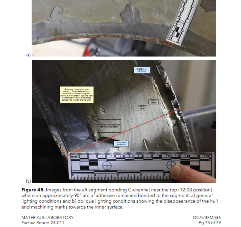
@TugboatEng, @IRstuff, @3DDave, @SWC, @Swinny, etc. Referencing "Figures 45 and 46" of the "Materials Laboratory Factual Report 24-011_Redacted-Rel.pdf" on page 73 of 79 (at least on the copy I downloaded over the weekend):

I am interested to hear/read others' interpretation of the possible causes of dis-bonding on the forward titanium ring in light of this photographic evidence of the adhesive conditions between the aft section of the cylinder and the aft titanium ring. More specifically, there is evidence (from the visible lines of the various pre-preg winding layers) that the adhesive contacted both the Ti ring and the CFRP cylinder on the outer two 1" co-bonded layers (layers 4 and 5). To put my following questions in context, I have very little experience with epoxy/fibre composites at all let alone being an expert on CF components bonded to Titanium components.

Questions:
1) It is my understanding that a properly spec'd and manufactured cured epoxy joint should fail through the epoxy or through the base material(s) rather than failing at the bonding layer(s) - in what circumstances / under what general conditions would a cured epoxy adhesive joint exhibit areas of failure as shown in Figures 45 b) and 46 a) i.e. failing at either bond layer and through the epoxy?
2) Looking at the fracture regions of the Ti flanges (specifically Fig 45 b) and Fig 46 a)) where the inner flange (i.e. the flange on the ID of the Ti ring) appears to have failed in shear as evidenced by the radial lines or "scratch" marks while the outer flange appears to have failed in a tearing or ripping mode as evidenced by the irregular surface of the outer flange (@TugboatEng has diagrammed above one possible failure geometry) on both the aft and forward rings - there are areas on a single radial cross section (see my red line on Fig 45 b) below, starting at the point the upper part of the ruler intersects the inner edge of the Ti Ring then drawing a radial line outwards to the outer edge of the Ti ring) where there appear to be regions of i) failure between Adhesive and Ti, ii) failure within the Adhesive, iii) failure between the Adhesive and CFRP hull, and iv) again between Adhesive and Ti; the only failure mode I can think of is de-lamination between co-bonded layers 3 and 4 as layers 1 through 3 travel inward during the rapid failure while the rapid release of energy somehow rips layers 4 and 5 outwards but I can't yet conceive of any free-body diagram that would account for the required forces - the only thing I am reasonably convinced of is that the failure could not have started through this specific radial cross section. Does this type of failure look familiar to anyone and if so, would you be so kind as to explain it?

2024-09-30_16_42_48-Materials_Laboratory_Factual_Report_24-011_Redacted-Rel_1_.pdf_-_Foxit_PhantomP_nlqtnu.png
- NOTE: red line and text markup is mine.
 
@DirteJoe, (for other readers) The first quote in your recent post from Sept 29, 2024 is from Pgs 5 & 6 (of 79) of Factual Report 24-011 and the second quote is from Pg 9 (of 79).
 
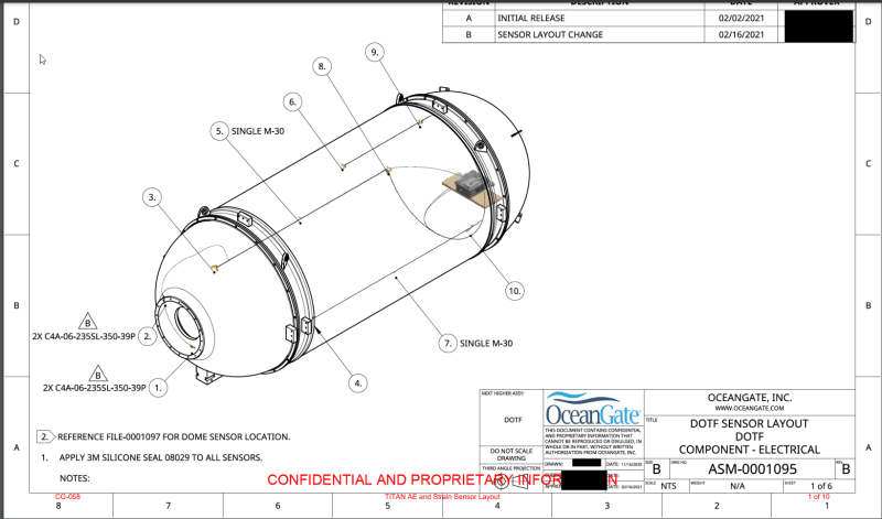
To any engineers with experience in acoustic monitoring (ideally with experience in measuring localized acoustic energy in rigid structures) - in the event of any acoustic-energy/emission-producing event in a rigid structure, would/should we expect to see that event measured at every measuring point (i.e. any Acoustic Emissions(AE) sensor) attached to the rigid structure? I assume that the event's signature would be attenuated and delayed as a function of the distance the AE sensor was from the location of the event and the medium(s) through which the energy was propagated but the bottom line is that I would expect to see that signature in all sensors. I am specifically referring to the testimony of Phil Brooks (Dir of Engineering at Oceangate (OG) from ~Jan 2021 to the accident **Edit: some time in 2023 after which time he resigned according to his testimony** whose focus was ostensibly on the electrical/electronic systems which included the RTM system) related to his explanation of the "strange" AE signatures (see around timestamp 6:25 and forward) across multiple sensors - specifically the AE Sensors 1, 3 and 5. In my opinion, his testimony in this regard generated more questions than answers. From the sensor location diagrams found at , Sensor groups 1 and 2 (details are apparently on File-0001097 which I can't find) are located very close to each other on the forward Ti dome. Groups 3 and 5 are on the same side of the hull but group 4 is closer to group 1 and group 3 is closer to group 2 and groups 4 and 2 record similar AE events - I don't have enough information on which to base a conclusion but I can't find a coherent theory that would explain this large of a discrepancy of AE measurements by ostensibly the same spec sensors without the AE sensors at locations 1, 3 and 5 to be damaged/out-of-spec/improperly-installed. I hope the NTSB's full investigation will shed more light on these discrepancies.

2024-09-30_18_40_09-CG-058_TITAN_AE_and_Strain_Sensor_Layout_Redacted.PDF_l6xppl.png
 
GF -
(I haven't dug deep into all the reports, but)
- the bond between the end of the composite hull and the Ti ring (the surface shown in the photos above) is completely useless structurally; trying to transfer load onto the end of a thick laminate is just not done by anyone with a clue; it could only be useful to seal the joint from water intrusion.
- the only bond joint that will have any structural purpose is between the Ti ring flanges and the surfaces of the composite hull; this is a typical shear joint. However, if there is differential radial displacement between the composite hull tube and the Ti ring that will introduce through thickness tensile stresses with are not desirable in a bonded joint.
- they claim to have used "spacers" to try to control the adhesive thickness; given all of the other poor fabrication practices shown in the various reports, I have no confidence that they properly used the spacers nor does it appear they actually inspected the bond lines.
 
AE just records internal "sounds".
It can sort of sometimes be used to triangulate the location of the sound.
It cannot indicate what created the sound. Relying on it for this application is just IMO foolish.
 
GreenFields said:
1) It is my understanding that a properly spec'd and manufactured cured epoxy joint should fail through the epoxy or through the base material(s) rather than failing at the bonding layer(s) - in what circumstances / under what general conditions would a cured epoxy adhesive joint exhibit areas of failure as shown in Figures 45 b) and 46 a) i.e. failing at either bond layer and through the epoxy?

There are three primary modes of failure for any adhesive joint:

1) Failure of the base bonded material. In this case, the adhesive itself does not fail; the base material(s) being bonded by the adhesive fail. This is easy to spot, as you wind up with one part having a perfect layer of adhesive still stuck to it, with a layer of material from the other bonded part still stuck to the adhesive on the far side. The failure happened when the surface of one of the parts was ripped off, without the adhesive coming apart.

2) 'Cohesive' failure, ie failure of the adhesive itself. This manifests as two parts separated, with each having a thin layer of remaining adhesive bonded to the surface at the joint.

3) 'Adhesive' failure, ie failure of the joint at the interface between the layer of adhesive and one of the parts.

These failure modes can be, and in fact almost always are, mixed. It would be very rare to test a joint to failure and have only a single one of these failure modes appear, unless certain conditions apply (very small parts, selected adhesive much, much stronger than base bonded materials, etc).

In the pictures we have of the failed bonded joints between the Ti rings and the composite hull section, we can see many large areas of adhesive failure, and a few areas appear to be cohesive failure as well. There do not appear to be any areas (at least none that I've seen so far) which exhibit failure of the base bonded materials. It is possible that some of the adhesive surfaces visible on the titanium rings (remember, if it's adhesive on the ring, the surface we can see was bonded to the CFRP shell) have a very thin layer of the composite resin still bonded to them. That resin is effectively transparent when it's very very thin, and it's possible there is a layer a few thousandths thick still bonded to the adhesive itself. So we can't completely eliminate base bonded material failure in these areas. All we can do at this point is, based on what we see elsewhere, state that it's unlikely.

There are whole engineering PhD thesis written on why and how adhesives fail, but in short:

Adhesive failure is really bad. It almost always indicates one of two possibilities; either the wrong adhesive product was selected (every adhesive can't properly bond every material, obviously) or the bonding faces were not properly prepared prior to bonding.

Based on the available information about the process used, those of us that have been following this for a while are not shocked that there are large areas of adhesive failure visible on both the titanium and CFRP parts of the assembly. All signs indicate that the surfaces were not well prepped when they were assembled.

GreenFields said:
2) Looking at the fracture regions of the Ti flanges (specifically Fig 45 b) and Fig 46 a)) where the inner flange (i.e. the flange on the ID of the Ti ring) appears to have failed in shear as evidenced by the radial lines or "scratch" marks while the outer flange appears to have failed in a tearing or ripping mode as evidenced by the irregular surface of the outer flange (@TugboatEng has diagrammed above one possible failure geometry) on both the aft and forward rings - there are areas on a single radial cross section (see my red line on Fig 45 b) below, starting at the point the upper part of the ruler intersects the inner edge of the Ti Ring then drawing a radial line outwards to the outer edge of the Ti ring) where there appear to be regions of i) failure between Adhesive and Ti, ii) failure within the Adhesive, iii) failure between the Adhesive and CFRP hull, and iv) again between Adhesive and Ti; the only failure mode I can think of is de-lamination between co-bonded layers 3 and 4 as layers 1 through 3 travel inward during the rapid failure while the rapid release of energy somehow rips layers 4 and 5 outwards but I can't yet conceive of any free-body diagram that would account for the required forces - the only thing I am reasonably convinced of is that the failure could not have started through this specific radial cross section. Does this type of failure look familiar to anyone and if so, would you be so kind as to explain it?

Before you do down the rabbit hole of trying to explain every mark or striation you see on the surfaces of these parts you have to keep in mind the external conditions the assembly was subjected to at the time of the failure.

At the time the hull imploded, the sub was at a depth of approximately 11,000 feet. At that depth, the water pressure is roughly 4900 psi. The OD of the hull was 66 inches, giving us about 3400 in² of cross sectional area. Do the math... the force pressing the end ring onto the hull was in the neighborhood of 16.5 million pounds. 8,300 tons.

The entire assembly was under an extreme amount of static load, with no structural redundancy of any kind. As soon as any component reaches a point where it can't support that extreme load, the resulting implosion happens extremely fast. We're talking about an event that was over in milliseconds.

The point is - an event involving the near-instantaneous release of that much potential energy is very, very chaotic. Modeling this failure with the best tools we have available would still be very difficult, and would likely leave a lot of unanswered questions.

In other words, we probably all agree that all the flanges being ripped off is peculiar, but an event this energetic is very difficult to model and why exactly the flanges failed the way they did is something we will potentially never know.
 
SwinnyGG said:
The entire assembly was under an extreme amount of static load, with no structural redundancy of any kind. As soon as any component reaches a point where it can't support that extreme load, the resulting implosion happens extremely fast. We're talking about an event that was over in milliseconds

This where I think Stockton Rush lost some of the necessary caution: it appears to me he normalized the very real totality of an implosion because no test to failure was done on the full size vehicle. Early, the 1/3 scale with CF domes was tested but the failure was a punch thru of one of the domes and not a total hull crush. The V1 hull was replaced due to cracks. It did not implode. It appears to me the relative success of the V1 and rebuilt V2, and OG FEA strengthened the over confidence Stockton had in the design factor/margin of the system.
 
I agree, that was one of the major failures.

The real root cause in my estimation is something I see in junior engineers A LOT.

His entire safety process was based on the idea that you can manufacture a critical component using edge-of-envelope techniques and materials, and end up with a result that has net design properties on the first try, with nearly zero process development.

I don't disagree that they would have been well served to much more thoroughly test the end product itself- but in my estimation, the fact that they were using the filament winding process right to the upper limit of what can be done with existing equipment was never even acknowledged, let alone evaluated as something that needed to be tested.

Rush just assumed that his hull would have net properties equivalent to much thinner, easier-to-fabricate structures, and never did any process eval to figure out if that was true.

 
It cannot indicate what created the sound. Relying on it for this application is just IMO foolish.

The one thing that Rush did semi-correctly was the inclusion of the strain gages, but, for whatever reason, no one did any real analysis with the data. Otherwise, both the hystersis in the strain and the changes after dive 80 would have rung alarm bells. This was possible consequence of hiring only junior engineers, who are open to new ideas, but don't know what the bad ideas learned through experience are.

Rush just assumed that his hull would have net properties equivalent to much thinner, easier-to-fabricate structures, and never did any process eval to figure out if that was true.

I think that was part of it, but there was a deep disdain of "conventional" design and verification, coupled with possibly different massive misunderstanding of why there are no other failures of DSVs, which was due to the massive amount of testing that he disdained, that he interpreted as being extremely overly cautious to the point of stifling "innovation."

Even smart people have massive blind spots.

TTFN (ta ta for now)
I can do absolutely anything. I'm an expert! faq731-376 forum1529 Entire Forum list
 
I have been watching the MBI session(s) in the links in Greenfield's post above, and realize I was wrong about OG testing to implosive failure. Phil Brooks, Dir. Of Eng. for a time, testifies OG tested the 1/3 scale hull #1 to implosive failure. The suddenness and totality was fully understood by all at the test. The resounding ringing in their ears left no doubt what had happened in the test chamber. The following 1/3 scales were tested to failure but did not implode. He indicates somewhat clumsily OG did plot strain data verses depth and not just time and he, Stockton and other OG staff reviewed the data. He said he is/was not an expert at interpretation of strain data but he/they looked for non-linear behaviors, shifts and offsets and could see in the 1/3 scale data definite, clear indications of impending failure.

I have become a stuck record with thinking the OG team had normalized the risk of implosion due to a lack of representative events and data; I have to reconsider this. It appears to me they did do testing (certainly, some of it was sloppy and incomplete), they had analysis but either the data and analysis does not scale with the final hull fabrication or the failure mode was not captured by the testing done.

Phil Brook's testimony is interesting.
 
Brian Malone said:
they looked for non-linear behaviors, shifts and offsets and could see in the 1/3 scale data definite, clear indications of impending failure.

This is an interesting revelation.

But it seems the next step for Rush et. al. was to just assume that since they had heard some noises from the scale hull prior to failure, they should just listen for those same noises in the full scale hull and everything would be fine unless they heard the same 'signature'.

If that's the logical path they took there definitely seems to be a scale model to full scale correlation/characterization step missing here.
 
Phil Brooks does say OG went straight to the "multi-cure" hull for the V2 hull and did not build a 1/3 scale test hull of this construction. I am pretty sure he confirms none of the 1/3 scale hulls were successful at reaching "Titanic" depth.
 
But it seems the next step for Rush et. al. was to just assume that since they had heard some noises from the scale hull prior to failure, they should just listen for those same noises in the full scale hull and everything would be fine unless they heard the same 'signature'.

But, they did hear a massive bang on Dive 80 (?), correlated to the change in the strain gage data, both of which they ignored. Both should have been indications that the hull was compromised in some way.

TTFN (ta ta for now)
I can do absolutely anything. I'm an expert! faq731-376 forum1529 Entire Forum list
 
Fully agree.

The only conclusion I can find (this is 100% conjecture) is the the 'loud bang' heard during dive 80 was assumed to not be a major problem because it didn't precisely match some 'ideal' sound signature they were looking for based on the test results from the 1/3rd scale tests to failure.

This whole thing reads to me as 'we heard a very specific thing during 1/3rd scale testing, as long as we don't hear that specific thing again we're good' as opposed to 'any signal above a certain threshold should trigger some sort of re-evaluation of the hull'.
 

Dr. Kramer of NTSB in his presentation, states what has been pointed out already: he did not receive data plotted strain vs. depth and tactfully states " it is a matter of opinion " whether OG's analysis method would have allowed for proper evaluation of hull behavior.
 
Phil Brooks states Electroimpact dictated the multi-cure hull fabrication method. Stockton was not keen on the method but acquiesced because Electroimpact would not take on the project if not a multi-cure design. I have not seen any Electroimpact personnnel testifying in the MBI videos.
 
The only conclusion I can find (this is 100% conjecture) is the the 'loud bang' heard during dive 80 was assumed to not be a major problem because it didn't precisely match some 'ideal' sound signature they were looking for based on the test results from the 1/3rd scale tests to failure.

That just makes everything even more moronic. Since when did a sample of one determine any sort of behavior?

I had a long drive today, and was thinking about Rush's gleeful exposition about "breaking the rules" and "progress" and I think that Rush had rushed to associate correlation with causation. While progress often does entail "breaking the rules," breaking the rules does not always entail progress, in most cases, in fact, it results in death or severe injury.

You would think that someone trained in engineering ought to know better, but apparently he was a legend in his own mind. Although, I suppose, he did, in fact, turn into a legend, albeit of a cautionary tale type.

TTFN (ta ta for now)
I can do absolutely anything. I'm an expert! faq731-376 forum1529 Entire Forum list
 

Part and Inventory Search

Sponsor