GreenFields said:
1) It is my understanding that a properly spec'd and manufactured cured epoxy joint should fail through the epoxy or through the base material(s) rather than failing at the bonding layer(s) - in what circumstances / under what general conditions would a cured epoxy adhesive joint exhibit areas of failure as shown in Figures 45 b) and 46 a) i.e. failing at either bond layer and through the epoxy?
There are three primary modes of failure for any adhesive joint:
1) Failure of the base bonded material. In this case, the adhesive itself does not fail; the base material(s) being bonded by the adhesive fail. This is easy to spot, as you wind up with one part having a perfect layer of adhesive still stuck to it, with a layer of material from the other bonded part still stuck to the adhesive on the far side. The failure happened when the surface of one of the parts was ripped off, without the adhesive coming apart.
2) 'Cohesive' failure, ie failure of the adhesive itself. This manifests as two parts separated, with each having a thin layer of remaining adhesive bonded to the surface at the joint.
3) 'Adhesive' failure, ie failure of the joint at the interface between the layer of adhesive and one of the parts.
These failure modes can be, and in fact almost always are, mixed. It would be very rare to test a joint to failure and have only a single one of these failure modes appear, unless certain conditions apply (very small parts, selected adhesive much, much stronger than base bonded materials, etc).
In the pictures we have of the failed bonded joints between the Ti rings and the composite hull section, we can see many large areas of adhesive failure, and a few areas appear to be cohesive failure as well. There do not appear to be any areas (at least none that I've seen so far) which exhibit failure of the base bonded materials. It is possible that some of the adhesive surfaces visible on the titanium rings (remember, if it's adhesive on the ring, the surface we can see was bonded to the CFRP shell) have a very thin layer of the composite resin still bonded to them. That resin is effectively transparent when it's very very thin, and it's possible there is a layer a few thousandths thick still bonded to the adhesive itself. So we can't completely eliminate base bonded material failure in these areas. All we can do at this point is, based on what we see elsewhere, state that it's unlikely.
There are whole engineering PhD thesis written on why and how adhesives fail, but in short:
Adhesive failure is really bad. It almost always indicates one of two possibilities; either the wrong adhesive product was selected (every adhesive can't properly bond every material, obviously) or the bonding faces were not properly prepared prior to bonding.
Based on the available information about the process used, those of us that have been following this for a while are not shocked that there are large areas of adhesive failure visible on both the titanium and CFRP parts of the assembly. All signs indicate that the surfaces were not well prepped when they were assembled.
GreenFields said:
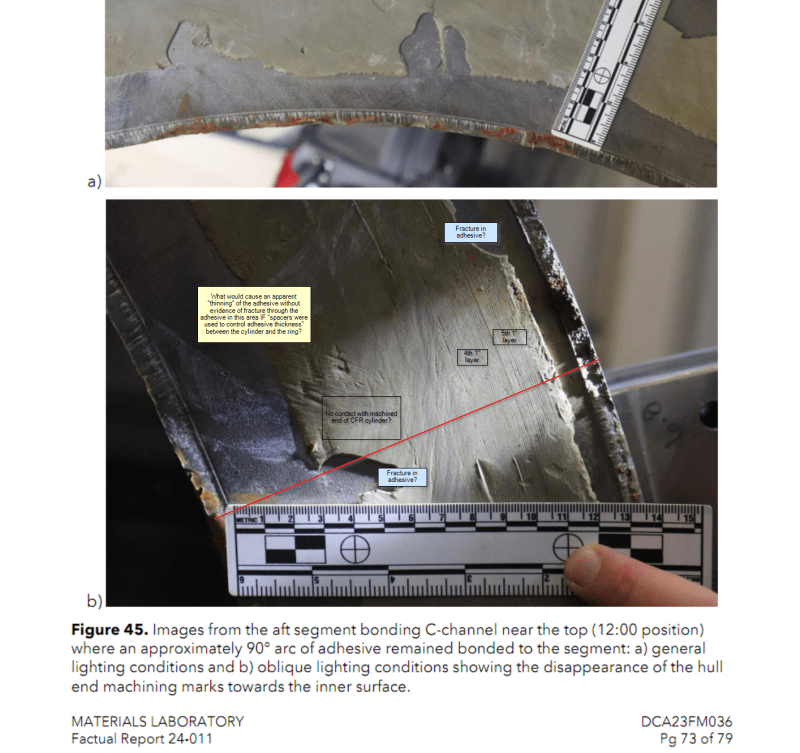
2) Looking at the fracture regions of the Ti flanges (specifically Fig 45 b) and Fig 46 a)) where the inner flange (i.e. the flange on the ID of the Ti ring) appears to have failed in shear as evidenced by the radial lines or "scratch" marks while the outer flange appears to have failed in a tearing or ripping mode as evidenced by the irregular surface of the outer flange (@TugboatEng has diagrammed above one possible failure geometry) on both the aft and forward rings - there are areas on a single radial cross section (see my red line on Fig 45 b) below, starting at the point the upper part of the ruler intersects the inner edge of the Ti Ring then drawing a radial line outwards to the outer edge of the Ti ring) where there appear to be regions of i) failure between Adhesive and Ti, ii) failure within the Adhesive, iii) failure between the Adhesive and CFRP hull, and iv) again between Adhesive and Ti; the only failure mode I can think of is de-lamination between co-bonded layers 3 and 4 as layers 1 through 3 travel inward during the rapid failure while the rapid release of energy somehow rips layers 4 and 5 outwards but I can't yet conceive of any free-body diagram that would account for the required forces - the only thing I am reasonably convinced of is that the failure could not have started through this specific radial cross section. Does this type of failure look familiar to anyone and if so, would you be so kind as to explain it?
Before you do down the rabbit hole of trying to explain every mark or striation you see on the surfaces of these parts you have to keep in mind the external conditions the assembly was subjected to at the time of the failure.
At the time the hull imploded, the sub was at a depth of approximately 11,000 feet. At that depth, the water pressure is roughly 4900 psi. The OD of the hull was 66 inches, giving us about 3400 in² of cross sectional area. Do the math... the force pressing the end ring onto the hull was in the neighborhood of
16.5 million pounds. 8,300 tons.
The entire assembly was under an extreme amount of static load, with no structural redundancy of any kind. As soon as any component reaches a point where it can't support that extreme load, the resulting implosion happens
extremely fast. We're talking about an event that was over in milliseconds.
The point is - an event involving the near-instantaneous release of that much potential energy is very, very chaotic. Modeling this failure with the best tools we have available would still be very difficult, and would likely leave a lot of unanswered questions.
In other words, we probably all agree that all the flanges being ripped off is peculiar, but an event this energetic is very difficult to model and why exactly the flanges failed the way they did is something we will potentially never know.