Continue to Site

Eng-Tips is the largest engineering community on the Internet

Intelligent Work Forums for Engineering Professionals

  • Congratulations waross on being selected by the Eng-Tips community for having the most helpful posts in the forums last week. Way to Go!

Tourist submersible visiting the Titanic is missing Part 2 69

Seeing the information above on the underwater explosions reminds me of this video- skip to 9:13 or so to see the effect: Specifically, he is shooting an oversized rifle into ballistic gel material intended to simulate, to some extent, typical flesh.
Of interest, you can see distinct flashes where the gel rebounds back into the cavity formed even after the bullet is long gone.
This guy has some interesting content if you can overlook some bluster- a lot of his videos are improved by skipping the first minute or so.

On the discussion of strength of the epoxy- concrete strength is considerably higher when confined, although normally measured in an unconfined condition- I wonder if this is taken into account here?
 
The drawings showing the hull being stepped where it connect to the end rings strike me as bad for several reasons.
If the hull is completely inserted into the groove in the ring, the strength of adhesive becomes less important.
It must hold the structure together on the surface when submerged, it becomes a seal and the water pressure tends to compress it with nowhere to go as it is confined by the ring.
Machining the hull slightly reduces the thickness.
With the end exposed water under pressure may be forced into the carbon fiber.
Once water is forced between the wound layers, it may follow the winding layers deeper and deeper into the thickness of the hull.
Water following the spiral wraps will proceed with both repeated dives and with time at depth, leading to progressive deterioration.
Please tell me that he ends were adequately sealed to prevent water entry.
--------------------
Ohm's law
Not just a good idea;
It's the LAW!
 
waross said:
Please tell me that he ends were adequately sealed to prevent water entry.

They coated the hull with rhino liner. That's it.
 
I could see water migrating into the CF hull, either through the sides protected with Rhino Liner (really??), or from the edges where the TI ends glued on.

I do not think Rhino Liner has been tested to be non-permeable at 5000psi.
 
TigerGuy link has very interesting content and additional discussions on that website.

waross said:
The drawings showing the hull being stepped where it connect to the end rings strike me as bad for several reasons

Yes, the stepped hull doesn't make sense other than to slightly reduce the total OD of the Ti interface rings. Maybe a cost of fabrication consideration? But at the size of the parts and materials being used, this seems unlikely that much cost reduction would have been realized by not enveloping the complete 5 inch thickness of the hull wall.
 
Anyone taken a shot at understanding the differential diametral strain between the carbon hull and the titanium ring? That they have similar sections and different modulus is a problem.
 
Having designed a few metal to composite joints, you don't do steps, you do tapered transitions. The 'impedance mismatch' between the stiffness of the two systems needs to be managed. If it were up to me the composite would be left as is and the tapering would be done in the metal.

Cheers

Greg Locock


New here? Try reading these, they might help FAQ731-376
 
Greg, what might that tapering look like? In this case, might it have been mitigated by adding a gradual taper to the inside of the ring, similar to this sketch?

Screenshot_2023-07-21_165309_ugosuh.png
 
The annular pockets in the interface rings are necessary to prevent putting the epoxy/adhesive joint in shear due to the deflection differential of the Ti interface rings and the CF hull, but inner lip of the pocket creates areas in the CF hull that would have been undergoing not only axial and radial compressive loading but also have bending moments imposed. The inner lips seem to have been rather short for what my gut feel says a longer engagement would have been good.
 
As I was posting wheaney has put up a great image.
 
I'm thinking more like this.

Screenshot_20230721-151155_zj0lsa.png
 
@TugboatEng, doesn't the abrupt transition (from right to left) still constitute a sudden mismatch in stiffness of the combined member? I would imagine that the idea of "slimming out" the Ti lip would be to ease the transition and avoid stress concentrations, while still having a low enough profile to be practical.
 
Yes, the gap in yellow needs to be much wider. This allows the adhesive to absorb the differences in strain. It's no different than an expansion joint. With that said, I don't know that the adhesive is strong enough to withstand the shear forces hence the addition titanium reinforcement underneath in green.

Screenshot_20230721-154809_iegdhj.png


There are still some step transitions. The fir tree joint was mentioned earlier. The key is that the titanium needs to support the end of the cylinder and as designed it doesn't.

Problem 2 is that the joint as designed traps air and epoxy which makes assembly difficult so I eliminated the outer step on the titanium ring in my finger sketch.
 
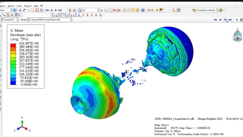
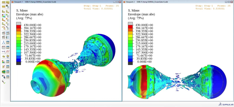
The engineering.com article uses images from
However, the simulation's author appears to not have accounted for the images of the recovered wreckage debris, wherein both end rings were recovered, while their simulation shows the end rings breaking. That would have only happened if the adhesive bond with the CF was stronger than the titanium; there's no way the CF implosion could have broken the titanium rings.

ring_cwh3du.jpg


TTFN (ta ta for now)
I can do absolutely anything. I'm an expert! faq731-376 forum1529 Entire Forum list
 
The author of the simulation has another video which shows a plan view with the rings breaking, but that's not the way the Titan broke. However, it seems possible that the rings deformed sufficiently that all the bolts broke, but the CF then broke away from the end rings and they regained their original shapes.

ring2_tzbwuz.jpg


TTFN (ta ta for now)
I can do absolutely anything. I'm an expert! faq731-376 forum1529 Entire Forum list
 
I, too, thought there was something wrong about how the interface rings shattered in the simulation.

I didn't look closely enough to see if the rings had their material set to Titanium or CFRP.

Perhaps he set the strength of the adhesive connecting the Ti to CFRP to be far higher than it was in practice, it was clearly not strong enough to deform and destroy the titanium, it simply let go.

I do believe that as the cylinder imploded, the face contacting the interface ring rotated and peeled the outer lip free, as shown in the debris photos. I think I'll try animating that - see attachment.

 
Given the use of paste adhesive between the ring and cylinder I don't see how they could have been assured of no voids in the bond line. I'd hope they applied clamping pressure between the two, but who knows?

The problem with sloppy work is that the supply FAR EXCEEDS the demand
 
I am not familiar with details on Abaqus. Does it have exaggeration added to deformations to help visualization? With others mentioning the disconnect between reality and simulation, I have zoomed in on the views and yeah, the interface rings' deflections look a little suspect.
 
SnTMan said:
...Given the use of paste adhesive between the ring and cylinder I don't see how they could have been assured of no voids in the bond line...

There are common techniques we use to reduce voids and entrapped air when joining assemblies with bonding paste. I was surprised to see in the video that they didn't do any such thing.
 

Part and Inventory Search

Sponsor