Eng-Tips is the largest engineering community on the Internet

Intelligent Work Forums for Engineering Professionals

  • Congratulations waross on being selected by the Tek-Tips community for having the most helpful posts in the forums last week. Way to Go!
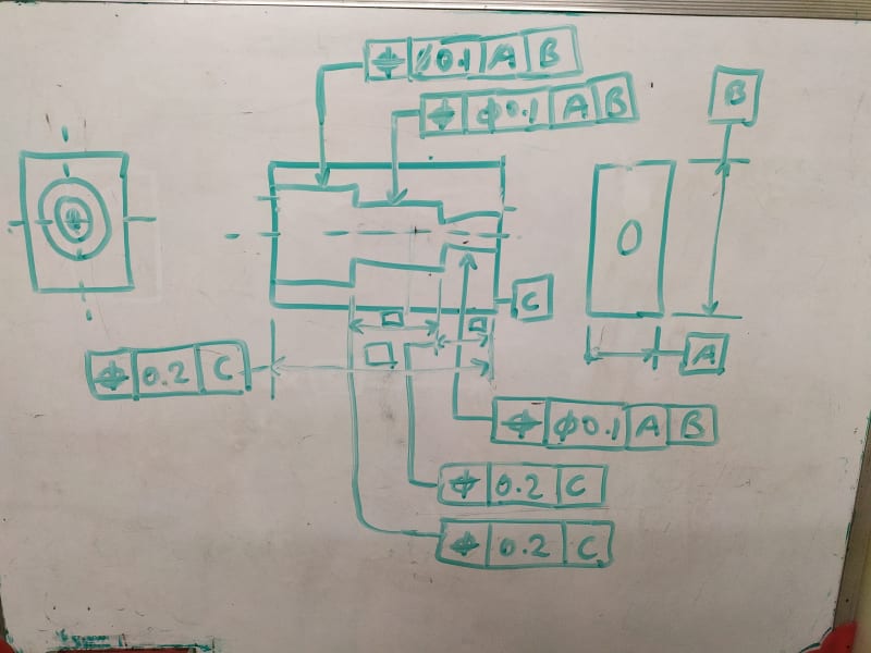
TP for stepped face

Status
Not open for further replies.

Sa-Ro

Industrial
Jul 15, 2019
273
0
0
IN
IMG_20200714_214925_okpssk.jpg


To define the stepped face (location), in what way datum A and B will support.

I think datum C alone will constrain the location and orientation within GT.
 
Replies continue below

Recommended for you

ASME doesn't allow position to be used on a face (surface). They would have you use profile of a surface.
Or should I presume you're using ISO, which does allow position?

Or... are you using position to locate the "feature of size" span across two faces?
 
ASME Y14.5:2018

Parallel to C and located from C

If we are using profile of surface, what way datum A and B will constrain.

Thank you.
 
If the flat faces need to be parallel to C and located from C, use profile of a surface with reference to C only. Make sure the leaders from the profile FCFs point to the surface and that the FCFs are not connected in any way to the extension lines or dimension lines of the basic dimensions.

The specification for the flat faces in your sketch does not reference A or B so I do not understand the question "what way datum A and B will constrain." They will not constrain any degrees of freedom for tolerances that do not reference them if this is what you are asking.
 
If A and B are specified as secondary and tertiary in the profile of a surface FCFs they will do nothing. C as primary constrains 2 rotational DOF and one translational DOF required for the full definition of the flat faces' location and orientation.
 
Status
Not open for further replies.
Back
Top