Continue to Site

Eng-Tips is the largest engineering community on the Internet

Intelligent Work Forums for Engineering Professionals

  • Congratulations KootK on being selected by the Eng-Tips community for having the most helpful posts in the forums last week. Way to Go!

Transfer Beam Torsion Design

Status
Not open for further replies.

struggle66

Civil/Environmental
Jul 5, 2013
127
T0rsi0n_u37zmc.png

Hi everyone,

Good Day,

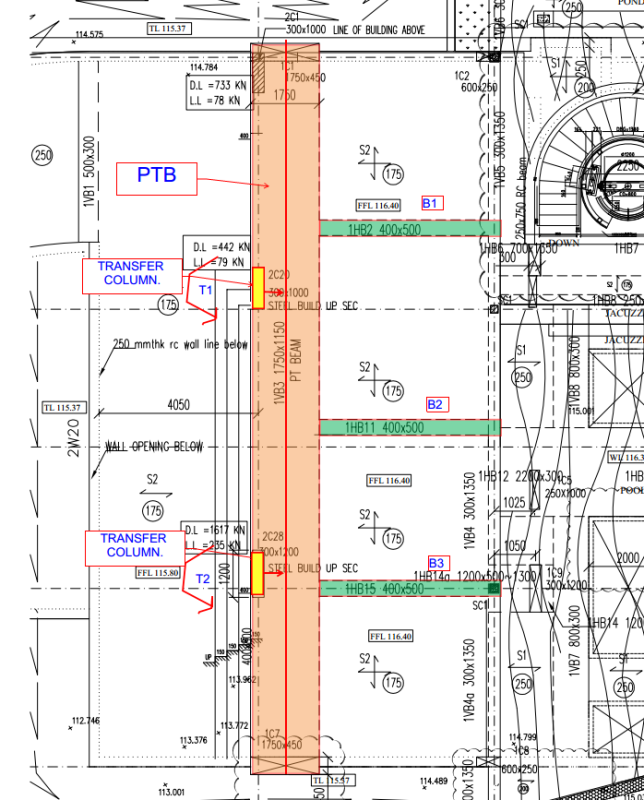
Please refer to above, I have a PTB supporting two transfer columns with eccentric torsion moments. The PTB section is not large enough for shear + torsion. I am thinking to use tie beams (B1, B2, B3) against the torsional rotation. Is it feasible?

If so, my questions are

(1) I understand that T2 will be directly resisted by B3. How about for T1? how will it distribute between B1 and B2. Will it distribute depending on the flexural stiffness and distance from the T1 of the each tie beam?

(2) If my tie beams can resist the torsional moment (T1 + T2), do I still need to design my main PTB for torsion?

Thanks
 
Replies continue below

Recommended for you

struggle66 said:
I am thinking to use tie beams (B1, B2, B3) against the torsional rotation. Is it feasible?

The concept is feasible. My gut feel is that your tie beams are too small to make a go of it. Ideally, I'd like to see:

1) Deeper tie beams. Wider too. Matching the column width would be nice.
2) Tie beams coming at the transfer column locations in all cases.
3) Tie beam reinforcing extending all the way to the left side of the PT transfer beam.

struggle66 said:
(1) I understand that T2 will be directly resisted by B3. How about for T1? how will it distribute between B1 and B2. Will it distribute depending on the flexural stiffness and distance from the T1 of the each tie beam?

In both cases, the load distribution will be a function of the relative flexural and torsional stiffness of the various members (PT transfer beam, tie beams, adjacent slabs).

struggle66 said:
(2) If my tie beams can resist the torsional moment (T1 + T2), do I still need to design my main PTB for torsion?

At minimum, I think that your beam should be adequately sized and reinforced for shear + compatibility torsion. Additionally, you may want to give some consideration to the serviceability implications of redistributing the torsion in this way. You'll get some torsional cracking prior to the redistributing the torsion.

I like to debate structural engineering theory -- a lot. If I challenge you on something, know that I'm doing so because I respect your opinion enough to either change it or adopt it.
 
Hi KootK,

Capture_bogfmj.jpg

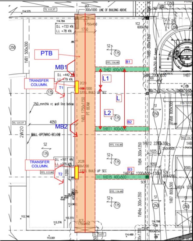
1. What is the percentage of T1 that will go to B1 and B2.

Is it Moment to B1 (@ left end of B1) MB1 = T1 x L2/L?

2. Any recommended software to do design torsion?

And again thanks!!
 
1) I would consider your proposal to be a valid way to estimate the upper bounds design forces on the tie beams. For the torsion design of the transfer beam, however, I'd recommend a more detailed analysis accounting for the relative flexural/torsional stiffnesses of the tie beams and transfer beam.

2) If your in-house PT software doesn't handle torsion design, an Excel/MathCAD spreadsheet of your own is probably the way to go.

I like to debate structural engineering theory -- a lot. If I challenge you on something, know that I'm doing so because I respect your opinion enough to either change it or adopt it.
 
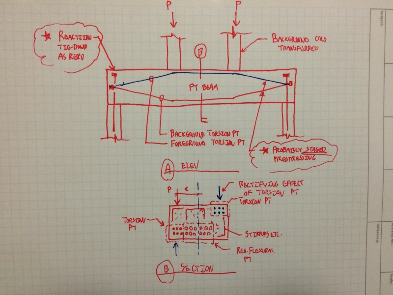
Perhaps you could use some strategically located post-tensioning strands in your beam to dial the torsion down to a manageable level internally. A little whacky, I know.

image_nolgsi.jpg


I like to debate structural engineering theory -- a lot. If I challenge you on something, know that I'm doing so because I respect your opinion enough to either change it or adopt it.
 
Hi KootK,

(1) In my tie beam concept, PTB cracks under torsion and I will provide more than minimum crack control torsion links.

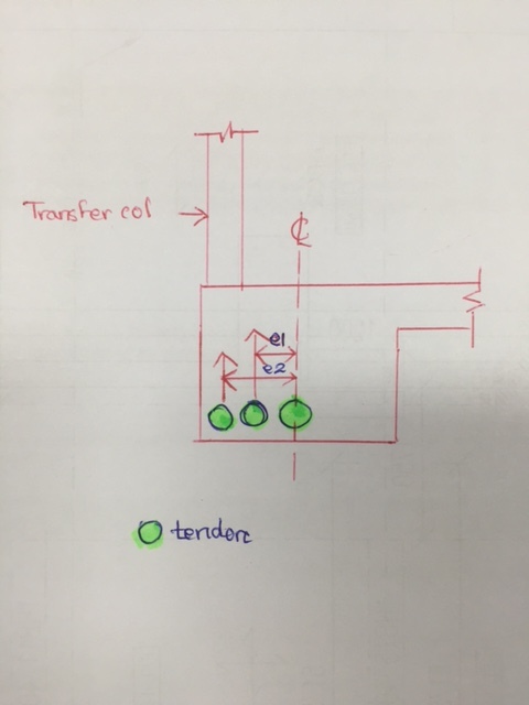
(2) I have this idea. "Instead of adding additional tendons for torsion, will it be better to position my flexural tendons unsymmetrical as shown below?" And still provide tie beams.
IMG_5197_zhcqbv.jpg

Thanks
 
I worry that your tendon layout will create a tendency for the girder to flex to the right and, when prevented from doing so by the adjacent slab, will result in a counterclockwise torsion in the girder which will undo some or all of what you're trying to accomplish. That said said, if you account for that and there's still a tangible benefit to your layou, then you might be on to something.

I like to debate structural engineering theory -- a lot. If I challenge you on something, know that I'm doing so because I respect your opinion enough to either change it or adopt it.
 
To some extent, I'm sure that your torsion will get absorbed in to your high and low slabs just as much as your relatively shallow tie beams. It's just still difficult to figure how much force goes where. A belt and suspenders approach surely has some merit here.

I like to debate structural engineering theory -- a lot. If I challenge you on something, know that I'm doing so because I respect your opinion enough to either change it or adopt it.
 
Been away at an all day AS3600 meeting, 16 hours with travel so no playing on computers yesterday.

I would prefer to have the transfer beam central on the transfer columns and take the torsion out at the end supports with a couple of transverse beams if possible. Or the transfer beam itself might be sufficiently stiff on 2/3 of the end columns as a cantilever.

For the current configuration, you would have to analyse it in 3D to see if the transverse beams are stiff enough to take out the torsion. With your current dimensions I would doubt it. I would prefer them to be the same depth at the transfer beam. The width would probably be ok in that case, but you need to analyse it to see what rotations you get.

Agree also that they would be better lining up. If they do not, you will have to design for the torsion developed for the column above causing torsion to get the reactions to the split transverse beams.

The torsion is not being caused by the prestress. You are allowing for the stresses to distribute evenly over the while beam shape plus flanges. To do so will cause torsion. I think you are playing games trying to get the tendons under the columns only. It may reduce the torsion slightly, but not worth the effort.

To design for torsion, all you need is your calculator to extend the shear calculations to allow for torsion. Good for the soul!!

Another question. Have you figured out how you are going to fit the end anchorages into the end column reinforcement and develop any moment connection you have there.

 
Hi

Thanks. I do not know how to express my gratitude to you Rapt, KootK and Ingenuity.

I wise you were my mentors :). My life will become much more easier and I will be able to contribute more to the society. I do not mind to self-study or go through the hard way. I just do not want to compromise the safety of people. Sometimes my knowledge are still very limited to go and study in depth. I really appreciate your help and all of your replies really enlighten me. Thanks. Any advice for my career. I think you two have gone through quite a lot of things in structural engineering?

Let me go back to torsion :).

My final tie beams size will be 700 mm x 700 mm. Today myself and structural consultant QP had a meeting with authority officer. They agreed the tie beam concept and asked me to just simply add quite a lot of torsion links and longitudinal bars. In this project, architect has a lot requirement. Main structural consultant is facing a lot of constraints.

Rapt said:
Another question. Have you figured out how you are going to fit the end anchorages into the end column reinforcement and develop any moment connection you have there.

Here in SG, it is common to terminate the column rebars below the PT anchorages and compensate by adding additional bars beside the anchorage with required sufficient lapping. Is there any wrong in it?

Thanks
 
struggle66 said:
I do not know how to express my gratitude to you Rapt, KootK and Ingenuity.

I want a couch to crash on when I make it out to Singapore for holiday.

Struggle66 said:
Here in SG, it is common to terminate the column rebars below the PT anchorages and compensate by adding additional bars beside the anchorage with required sufficient lapping. Is there any wrong in it

Depends what the final lapping detail looks like spatially and whether or not you need to be able provide a moment/torsion connection between your column and transfer girder.


I like to debate structural engineering theory -- a lot. If I challenge you on something, know that I'm doing so because I respect your opinion enough to either change it or adopt it.
 
Remember your "Tie" beam is actually flexural with its main loading being a moment at the transfer beam end. You are going to have to develop the reinforcement in the top right to the back of the transfer beam, tieing in with some good ties in the beam.

RE the column reinforcement, what Kootk said! I cannot understand why you cannot detail the column reinforcement to be continuous to the top and develop into the transfer beam. You know the dimensions of all of the anchorages. Plan their positions logically so that they interfere with the least bars and detail the bar positions to fit. And make sure the builder gets them in the correct positions because they cannot move after the column is poured and before the anchorages placed. Even get them to put in dummy anchorage box outs for the column pour to make sure it all fits.

It will be best to try to put 2 or 3 anchorages in one vertical plane to interfere with the least number of column bars, so they will have to transition sideways to their final position further along the beam.

PS don't worry about the couch for me, the best Kari Laksa in Singapore will be sufficient.
 
Both of you are quite welcome. I've met rapt in person. Hope I can meet KootK one day.
 
Status
Not open for further replies.

Part and Inventory Search

Sponsor