struggle66 said:
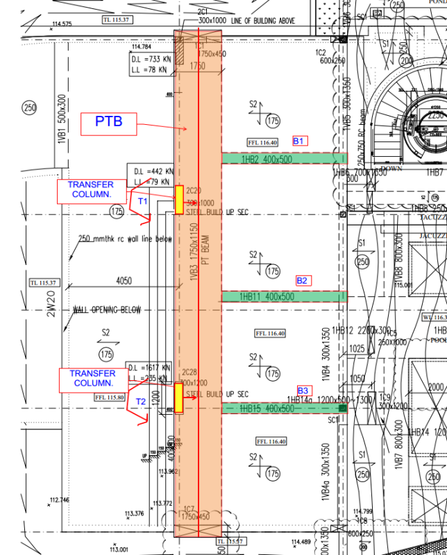
I am thinking to use tie beams (B1, B2, B3) against the torsional rotation. Is it feasible?
The
concept is feasible. My gut feel is that your tie beams are too small to make a go of it. Ideally, I'd like to see:
1) Deeper tie beams. Wider too. Matching the column width would be nice.
2) Tie beams coming at the transfer column locations in all cases.
3) Tie beam reinforcing extending all the way to the left side of the PT transfer beam.
struggle66 said:
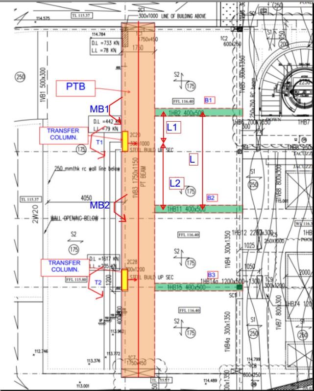
(1) I understand that T2 will be directly resisted by B3. How about for T1? how will it distribute between B1 and B2. Will it distribute depending on the flexural stiffness and distance from the T1 of the each tie beam?
In both cases, the load distribution will be a function of the relative flexural and torsional stiffness of the various members (PT transfer beam, tie beams, adjacent slabs).
struggle66 said:
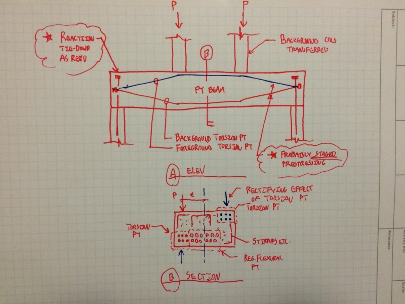
(2) If my tie beams can resist the torsional moment (T1 + T2), do I still need to design my main PTB for torsion?
At minimum, I think that your beam should be adequately sized and reinforced for shear +
compatibility torsion. Additionally, you may want to give some consideration to the serviceability implications of redistributing the torsion in this way. You'll get some torsional cracking prior to the redistributing the torsion.
I like to debate structural engineering theory -- a lot. If I challenge you on something, know that I'm doing so because I respect your opinion enough to either change it or adopt it.
") . My life will become much more easier and I will be able to contribute more to the society. I do not mind to self-study or go through the hard way. I just do not want to compromise the safety of people. Sometimes my knowledge are still very limited to go and study in depth. I really appreciate your help and all of your replies really enlighten me. Thanks. Any advice for my career. I think you two have gone through quite a lot of things in structural engineering?
. My life will become much more easier and I will be able to contribute more to the society. I do not mind to self-study or go through the hard way. I just do not want to compromise the safety of people. Sometimes my knowledge are still very limited to go and study in depth. I really appreciate your help and all of your replies really enlighten me. Thanks. Any advice for my career. I think you two have gone through quite a lot of things in structural engineering?