MD88
Electrical
- Mar 5, 2020
- 9
Hello,
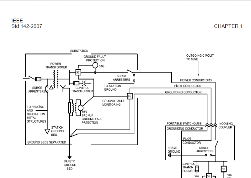
As per CSA M421, and I think several other mining electrical codes around the world, the ground potential rise (GPR) is limited to 100V for underground and open pit mines. Since the GPR at the main utility tie sub is usually much higher than this, the UG mine substation power grounding system needs to be isolated from the plant ground system.
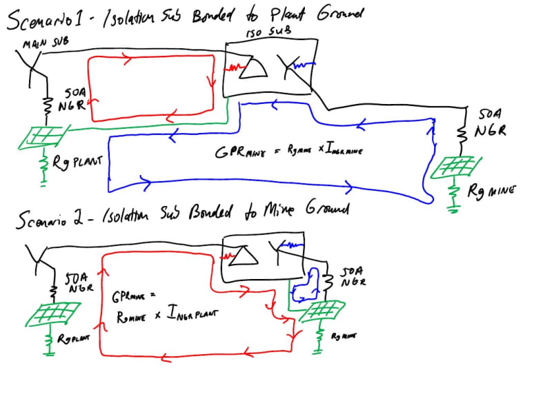
I've previously seen a design where the overhead line from the main plant substation came in to an "isolation transformer", and the ground grid at this transformer was connected to plant ground, but the neutral grounding resistor (NGR) connected to that transformer wye was located a certain distance away from this substation, and connected to a separate ground grid. The shields and ground wire on the phase cables from the transformer secondary to the UG distribution were insulated from ground at the transformer secondary, and connected to the separate grid as well.
I understand how this prevents the GPR from the utility tie sub from being transferred... and faults on the transformer secondary windings to the tank would follow a path back to utility tie sub grid via the skywire, through remote ground, and up through the separate mine ground. The fault current would be limited by NGR of the isolation transformer, and the GPR of the mine would be the Rg of the mine grid X the NGR current of the isolation transformer.
I'm struggling to see why the isolation transformer tank was bonded to plant ground, while the NGR was tied to mine ground (note that both NGRs were the same amperage). If the isolation transformer tank was bonded to mine ground instead, it would be faults on the primary windings to the tank that would go through remote ground and would equally be limited by the utility tie sub NGR (since it was the same amperage), and the GPR of the mine grid would be Rg of the mine grid X the NGR current at the utility sub... I think??
Maybe I'm having a brain fart, or maybe the design I saw wasn't necessary... any input would be appreciated.


