Continue to Site

Eng-Tips is the largest engineering community on the Internet

Intelligent Work Forums for Engineering Professionals

  • Congratulations SDETERS on being selected by the Eng-Tips community for having the most helpful posts in the forums last week. Way to Go!

True position applied to planes 3

Status
Not open for further replies.

Rwelch9

Mechanical
Apr 22, 2020
116
IMG_20200612_223343_knrvks.jpg

Hi ,


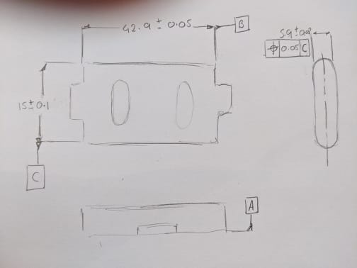
I have a couple of queries about the sketch i did .

Datum feature C would this be a derived line between the two axis of the radii at each end of the component

The True position call out ± 0.05 to Datum feature C , is this a valid call out ?

Thanks

R
 
Replies continue below

Recommended for you

Datum feature C would this be a derived line between the two axis of the radii at each end of the component
Datum feature C is the feature-of-size width dimensioned as 15 ± 0.1. The way C is referenced in the position feature control frame, Datum C would be the center plane of that width when simulated with 2 parallel planes collapsing from the outsides until they hit the high points.
That's the strict answer to your first question. However, you also labeled a datum feature A and a datum feature B but they aren't referenced anywhere; maybe this is an incomplete sketch, but I also wonder if you meant to reference A and B in that position callout, ahead of C.

The True position call out ± 0.05 to Datum feature C , is this a valid call out?
It's not a position callout of ±0.05, just 0.05. But yes, it's valid.
I have a few questions about the sketch, such as what that right-hand view is supposed to be. (A detail view of one of the slots?) Also, Is the length of 42.9 meant to be a "continuous feature" or just the width down to where the two tabs stick out?
Anyhow... I hope that helps.


John-Paul Belanger
Certified Sr. GD&T Professional
Geometric Learning Systems
 
Belanger said:
I have a few questions about the sketch, such as what that right-hand view is supposed to be. (A detail view of one of the slots?)

From the way that view is positioned and the fact that the height of the feature matches and aligned with the 15+-0.1 height size at the view to the left of it, I concluded that this is a side view of the part (with 2 horizontal lines missing in the middle to show the tab) and that the 15+-0.1 feature is with rounded ends. This is also suggested by the way the question was asked:
"Datum feature C would this be a derived line between the two axis of the radii at each end of the component?"(the answer is no anyway).

Rwelch9,
If I am right I think datum feature C is a questionable primary datum feature for the position control (especially at RMB).
If I am wrong and this is a detail view of one of the slots as suggested by Belanger, then with only datum feature C referenced it would control orientation only, leaving the location left-right uncontrolled.

I think Belanger's question should be answered before anything else can be properly addressed.
 
Belanger + Burunduk

Datum feature C is derived from two cylinders . This is what what confusing to me . As i thought maybe Datum C was a derived mid axis between the two cylinders rather than a plane ?

Yes sorry this in an incomplete drawing and quick sketch , as my main focus was Datum C.

The detail on the right , again was just a quick sketch of the plan view , again as these are cylinders not planes ( apologies on the poor sketch )

I had the same question of Datum B , which is a CF

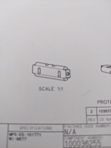
See attache Picture to get a clear understand of shape. Datum feature is with my take the mid axis derived between the two out side Radii.


Thanks

R

IMG_20200614_103734_bv3oek.jpg
 
Rwelch9,
I assume that like with the previous part, you work with ASME Y14.5 on this too.

Do you know what the position tolerance referencing C attempts to achieve for the 5.9 width feature? I'm not sure I understand the design intent here.

Also, are there any other dimensions and tolerances that control the radii other than the 5.9 width and the 15 dimension of the distance between them (For example basic radius and profile)? And how is the part assembled with its mating parts?
 
Yes all ASME ,

So the planes the make up the 5.9mm width . this does not get machined as one profile, due to cutter deflection .

So theoretically the plane derived from the 5.9mm width could be way off from the center of the radii. So i think this is trying to control this.

The only other control for Datum C is a perpendicular call out to Datum B .

Everything in my drawing looks okay except, i am trying to get my head around checking the mid plane derived from 5.9mm planes , positionally to Datum feature C and trying to figure out if this is a valid call out .

Position call outs much more seen with holes etc.


Thanks

R


To understand what datum(s) should be derived from datum feature C I would approach this through the datum feature simulator:

The standard specifies that the datum feature simulator shall of the inverse shape of the datum feature unless otherwise specified. Therefore I would conclude in this case that it should be two internal half-cylinders with adjustable spacing that you can reduce until contact is made with the external half cylinders of the datum feature. The datums I would associate with it are a plane that passes through the two axes of the internal half cylinders of the datum feature simulator (call it datum plane (1)) and another plane (2) perpendicular to the first at the middle of the distance between the axes. The positional tolerance referencing C can control the centering of the 5.9 width feature to plane (1).

To problem is that there is no basic geometry (true profile) to the two 2.95 (5.9/2) radii and it can be argued that the 2 half-cylinders of the datum feature simulator should be also adjustable at size, not just at separation. I'm interested to read what the others here think. This is not a simple or typical case.

By the way, there is also a problem with datum feature B being CF. If its size is associated with the CF symbol as you say, this causes an issue due to the connection between the CF concept and rule#1, in conjunction with the fact that the interruptions are external tabs and not internal slots. I don't know if you want to get into this. It concerns whoever made the drawing.
 
Burunduk,

My issue i have a lot of the time is not with the logic, more the correct application .

To create a datum simulator to the accuracy required to be considered a true inverse shape . How do you check that ? do you make another simulator etc.

Datum and datum feature simulators work extremely well for me with a solid block sitting and pushing up against solid , flat faces. I am struggling to create simulators that truly react with the Datum feature as it would as a functional part

This where my reliance on the CMM has been extremely heavy, although i am aware this result on the CMM has its own major level of measurement uncertainty.

Is datum feature C a mid line or mid plane ? I find this a very difficult Datum feature as a tertiary and try to get the correct DRF set up.

My thoughts on the basic geometry , i thought the basic values would be zero. The mid plane of the 5.9 width regardless of size should be central to the cylinders. ?


Thanks

R


Rwelch9, your concerns are well-founded. Can you push for a change in the drawing?

Although It depends on the function of the part, of course; the only case where this datum feature is a reasonable choice is that the part is assembled into some sort of rail with its radii contacting the mating part - sliding in something that looks like the datum feature simulator I described.

A simpler alternative for inspection purposes would probably be selecting the 5.9 as a datum feature and controlling the radii by profile referencing the width as primary and datum feature B as secondary (especially since you say that perpendicularly is specified for this feature to B anyway - so it could be replaced by this profile control too). It might not be a bad scheme even if the function suggests the radii as a datum feature. Perhaps it's one of these cases where functional datum feature selection should be overridden in favor of manufacturing/inspection efficiency.
 
Rwelch9 said:
Is datum feature C a mid line or mid plane ?

I would treat it as a datum feature creating a datum centerplane (and another plane normal to it) as described in my post from 14 Jun 20 21:27.
 
Burunduk

I am seeing more and more designers using position to control planes . when does this work well and when you use this over surface of profile ?


Thanks


R
 
If by "to control planes" you mean center planes of width-type features of size such as shown in your sketch, it works well for symmetrical relationships or basically defined location where the datum feature is also a width-type feature. It's also possible to locate a width-type feature to a datum axis. In your case, the datum feature is difficult to handle but generally a position FCF under a width dimension is perfectly acceptable.
 
In general however if you wanted to control a planes location and orientation to a DRF , would it be more common to use Surface of a profile ?

or would it depend on a number of different things

I am not talking about center planes more so actual plane features you can touch.

Thanks

R
 
Per the ASME standard, you can't use position on plane surfaces. Only on feature of size. In ISO plane surfaces can be controlled for location by position.

Yes, per ASME profile of a surface is the correct control for this.
 
Burnuduk

Thank you for your answers they are appreciated .

So position can me mid planes etc.

If it is physical plane like out side edge or face of a component , then surface of a profile is the best option ?

Thanks

R
 
Rwelch9 said:
If it is physical plane like out side edge or face of a component , then surface of a profile is the best option ?

If you want to control its location relative to a datum per ASME, it's not just the best option but the only option.
 
The standard specifies that the datum feature simulator shall of the inverse shape of the datum feature unless otherwise specified. Therefore I would conclude in this case that it should be two internal half-cylinders with adjustable spacing that you can reduce until contact is made with the external half cylinders of the datum feature. The datums I would associate with it are a plane that passes through the two axes of the internal half cylinders of the datum feature simulator (call it datum plane (1)) and another plane (2) perpendicular to the first at the middle of the distance between the axes. The positional tolerance referencing C can control the centering of the 5.9 width feature to plane (1).

To problem is that there is no basic geometry (true profile) to the two 2.95 (5.9/2) radii and it can be argued that the 2 half-cylinders of the datum feature simulator should be also adjustable at size, not just at separation. I'm interested to read what the others here think. This is not a simple or typical case.

Unless I missed something and some other application of the datum feature symbol was suggested, I would have to disagree - this is not the way it is drawn. As JP noted, but was omitted in the discussion following, is that the datum feature symbol applied to the 15+/-0.1 width suggests only a width shaped datum feature and simulator, ie: it would be simulated by two parallel planes contracting upon the opposed half-cylinders. If that is not the intent, the drawing needs to be changed - for example a 2X profile tolerance applied to the pair of radii and a datum feature symbol applied to the profile tolerance.

A width-shaped datum feature, besides possibly not being the intent, would make a very poor primary datum feature - as it is referenced in the OP drawing. It would be a very unstable datum feature and your parallel plane simulators would have a tendency to contract without limit (ie: no minimum). I showed this in an old thread ( my post on 18 Mar 19 16:54) - my intent in that thread was to show such a result from extreme deviation from a nominally flat surface however the same behavior would result from the case in question.
 
chez311,

This (parallel planes datum feature simulator contacting the high points on the half-cylinders) was my initial thought too, but please refer to para. 4.5 in ASME Y14.5-2009:

"4.5 DATUM FEATURE SIMULATOR
A datum feature simulator, as defined in para. 1.3.17, shall be the inverse shape of the datum feature, unless othrwise specified. See Figs. 4-10, 4-11, 4-12, 4-13, and 4-14."

Unless this changed in the 2018 standard (which the OP mentioned using in another thread) the definition in the standard applies. Since the feature is not parallel surfaces width-type feature but two radii (could be considered as "two opposed parallel elements" regular feature of size), the datum feature simulator shall be of the inverse shape of the feature, and though we are used to seeing directly toleranced dimensions applied either to cylindrical or width-type features, nothing in the standard defines that a directly toleranced dimension always imposes the use of parallel planes (or cylinder) datum feature simulator. Rather the shape of the datum feature simulator is decided by the shape of the datum feature, not by the type of dimension given.

It was also confirmed further down the thread that the scheme shown in the drawing is not recommended and a profile of a surface specification for the radii was suggested instead, in combination with the 5.9 width selected as a primary datum feature reference for the profile control, to achieve the type of radii-to-width "centering" intended by the designer when applying the position control being discussed.
 
I am aware of the wording of 4.5 - this is not the way the datum feature symbol is applied or what the wording suggests. It has nothing (or at least very little) to do with the way the tolerances are applied (though none are shown in the sketch applied to the radii besides the width dimension) -* the datum feature symbol is applied to the width, therefore your datum feature is the width and the datum feature simulator is width-shaped.

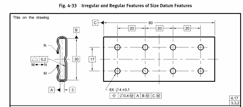
See Y14.5-2009 fig 4-33 datum feature A.

fig_4-33_sjrn7i.png


*Edit: I decided to strike this portion. I should clarify, it is not dictated purely by the way the tolerances are applied, but by the way the datum feature symbol is applied to the tolerances. Sort of a nuanced distinction to make I know but let me be perfectly clear - it would not matter if the width were basic or directly toleranced, either way if the datum feature symbol is applied to the width as shown it would imply the simulator is width-shaped.
 
chez311 said:
I should clarify, it is not dictated purely by the way the tolerances are applied, but by the way the datum feature symbol is applied to the tolerances.

I'm used to thinking that the datum feature symbol is applied to features, not to tolerances. It is usually associated with the size dimension for features of size.

chez311 said:
Sort of a nuanced distinction to make I know but let me be perfectly clear - it would not matter if the width were basic or directly toleranced, either way if the datum feature symbol is applied to the width as shown it would imply the simulator is width-shaped.

Either basic or directly toleranced - so what matters is not how it's applied "to the tolerances" is it? Then is it just the datum feature being associated with a size linear dimension that makes the simulator be two parallel planes? And para. 4.5 - it does not apply to features of size (other than when it's associated with a profile tolerance for the irregular ones)?

I can't see how the wording of 4.5 can suggest anything other than what it explicitly states.
 
Status
Not open for further replies.

Part and Inventory Search

Sponsor